Project Overview
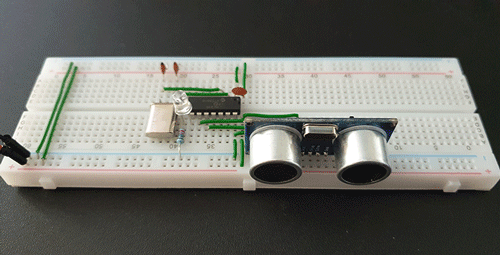
The circuit implements the HC-SR04 ultrasonic sensor with a PIC16F630 microcontroller and it flashes a LED diode when an object is within 1 metre. The rate of the flashes is relevant to the distance between the object and the sensor.
The source code is written in C language under MPLAB X IDE and compiled with XC8 compiler.
The Hardware
HC-SR04
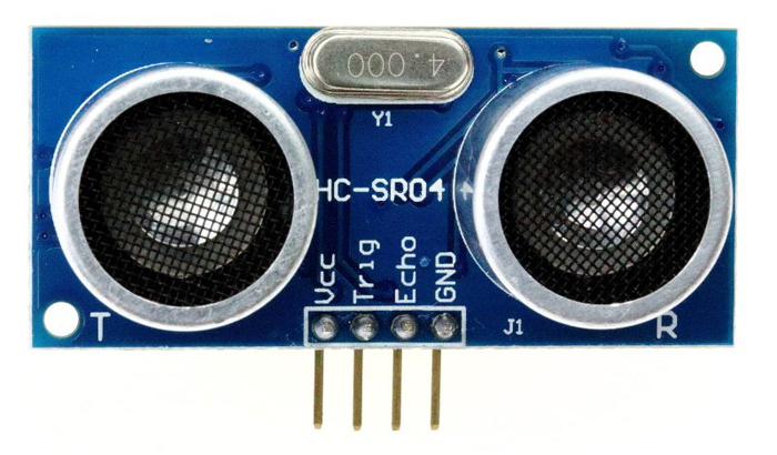
The HC-SR04 sends out ultrasonic pulses when the “Triger” pin is high (+5V). When the bounced waves are returned to the sensor, the “Echo” pin is set to high (+5V). It stays high for the same length of time as the wave pulse took to return back. It also includes the waves’s time to get to the target. Therefore the elapsed time has to be divided by 2.
This is a fairly cheap sensor which works nearly perfectly. The only and obvious problem I found is when the waves are hitting an object which is in an angle to the sensor. The waves are not returning back to the receiver, instead of they bouncing away from it. It only works with surfaces flat to the ultrasonic transmitter / receiver.
For more technical details, please see the HC-SR04’s user manual (PDF).
PIC16F630 Microcontroller
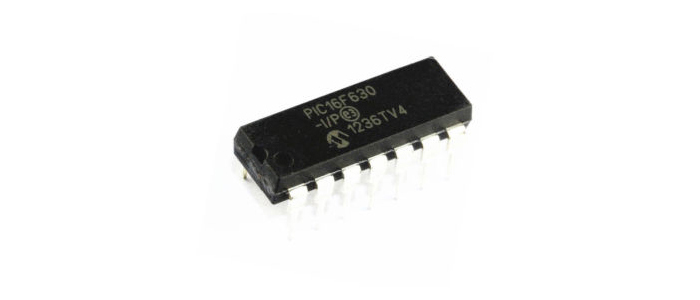
This is a 14 pin 8-bit microcontroller with a tiny 1.75KB of program data memory and only 64Byte of SRAM size. It is a simple and limited MCU which is ideal for the purpose of this project. I wanted to keep everything as simple as possible.
The microcontroller is operated at 5V (max. 5.5V) and capable of supplying the same power on its outputs. It has 2 data channels (A and C) with 8 I/O pins per channel. Also has a built-in timer, which I used to measure the time for the wave pulses to return back to the sensor. From that data, the distance can be calculated.
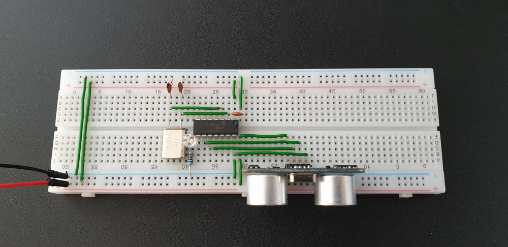
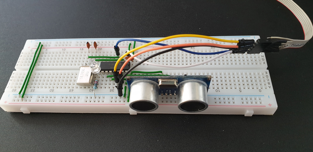
The Schematic Diagram
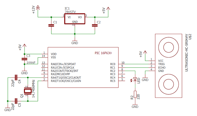
By looking at the circuit diagram we can tell how simply the parts are connected together. The MCU is running at 14.7456MHz (same as the crystal oscillator). The ultrasonic sensor is wired to the microcontroller’s I/O pin 9 & 10. Pin 8 operates the LED diode which has a 220Ω resistor before ground. C3 is a 100nF (0.1uF) ceramic capacitor for noise reductions to provide a stable operation.

Ultrasonic Distance Sensor Schematic Diagram (PDF)
On the top of the diagram, there is circuit for the recommended power supply. I didn’t include it on my breadboard as I had a continuous +5V power supply.
Source Code
It builds up from 2 files, the header for configuration and the main code written in C language. Due to the small program data memory size of the PIC16F630 the code had to be short and simple.
/*
 * File:   pic16f630_distance_sensor.h
 * Author: gellai.com
 *
 */

#include <xc.h>
#define _XTAL_FREQ 14745600     // Crystal at 14.7456MHz

#pragma config FOSC = HS        // External oscillator
#pragma config WDTE = OFF       // Watchdog timer disabled
#pragma config PWRTE = OFF      // Power-up timer disabled
#pragma config MCLRE = OFF      // RA3/MCLR pin function select disabled
#pragma config BOREN = ON       // Brown-out detect enabled
#pragma config CP = OFF         // Code protection disabled
#pragma config CPD = OFF        // Data code protection disabled

#define LED RC2                 // LED on PIN 8
#define TRIGGER RC0             // Sonar trigger on PIN 10
#define ECHO RC1                // Sonar echo on PIN 9

void delay_ms(int);
/*
 * File:   pic16f630_distance_sensor.c
 * Author: gellai.com
 */

#include "pic16f630_distance_sensor.h"

void main()
{
    int dist_cm;

    TRISC = 0x02;   // RC1 input
    PORTC = 0x00;   // All I/O on PortC to low
    T1CON = 0x20;   // 1:4 prescale value and internal timer

    while(1) {
        TMR1L = 0;
        TMR1H = 0;

        // Set trigger high for 10 micorseconds
        TRIGGER = 1;
        __delay_us(10);
        TRIGGER = 0;

        // Start timer when echo is high
        while(!ECHO)
            ;
            TMR1ON = 1;

        // Stop timer when echo is low
        while(ECHO)
            ;
            TMR1ON = 0;

        // Calculate distance in centimetres
        // 54.212 is a calculated value
        dist_cm = ( TMR1L | (TMR1H << 8) ) / 54.212;

        // Distance is between 0 and 400cm
        if(dist_cm > 0 && dist_cm < 400) {
            // Turn LED on under 5cm
            if(dist_cm > 0 && dist_cm <= 5) {
                LED = 1;
            }
            // Flash LED under 100cm with a variable rate
            else if(dist_cm > 5 && dist_cm < 100) {
                dist_cm *= 5;
                LED = 1;
                delay_ms(dist_cm);
                LED = 0;
                delay_ms(dist_cm);
            }
            // Turn LED off
            else {
                LED = 0;
            }
        }

        delay_ms(10);
    }
}

// Delay function in milliseconds
void delay_ms(int ms)
{
    while(ms > 0) {
        __delay_ms(1);
        ms--;
    }
}
Compiled code: pic16f630_distance_sensor.hex
‘Trigger’ pin is set to high (+5V) for 10 microseconds. It sends a wave pulse out, which bounces back from the object front of it. The ‘Echo’ pin shifts to high (+5V) for as long as the wave to take to reach the sensor’s receiver. From this data the distance can be calculated. It involves the settings of the timer and the internal clock of the MCU; the speed of the crystal connected to it.
T1CON = 0x20; means that the prescale value is set to 1:4 and we are using the internal timer which is the frequency of crystal oscillator divided by four (FOSC / 4). It is a division by 4 and nothing to do with the prescale value. There are more details about the timer settings in the PIC16F630 Datasheet on page 36.
TMR1L & TMR1H are together the 16-bit timer/counter which consist two 8-bit registers. From their values we can calculate the object’s distance.
Calculations
What does ( TMR1L | (TMR1H << 8) ) / 54.212 do?
TMR1L | (TMR1H << 8) merges the two 8-bit registers together. TMR1H is shifted to the left with 8 bits and then TMR1L is added after it.
54.212 is a divider which has to be calculated based on the prescale value (in my case is set to 4) and the crystal oscillator’s frequency.
Time Calculation
First we need to calculate the elapsed time.
Time = (TMR1H:TMR1L) * (1 / Internal Clock) * Prescale
Internal Clock = FOSC / 4 = 14745600Hz / 4 = 3686400Hz
Time = (TMR1H:TMR1L) * (1 / 3686400) * 4
Time = (TMR1H:TMR1L) * 4 / 3686400
Time = (TMR1H:TMR1L) / 921600
Distance Calculation
The distance of the object is measured in centimetres.
Distance = (34000 * Time) / 2
The speed of sound (ultrasonic wave) in air is 340m/s = 34000cm/s.
Distance = (34000 * (TMR1H:TMR1L) / 921600) / 2
Distance ≈ (TMR1H:TMR1L) / 54.212
Programming The MCU
This can be done with various programmers and softwares. I used Microchip’s PICkit 2 programmer, which is affordable and supports a wide range of microcontrollers.
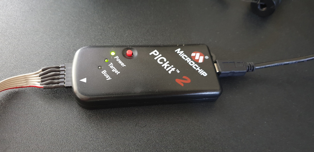
The following pins are required on the PIC16F630 to program it:
| PICkit 2 Pin No. | Name | PIC16F630 Pin No. |
| 1 | VPP/MCLR | 4 |
| 2 | VDD (Target) | 1 |
| 3 | VSS (Ground) | 14 |
| 4 | ICSPDAT | 13 |
| 5 | ICSPCLK | 12 |
| 6 | AUX | NOT CONNECTED |
After successful programming we can supply 5V to it and test out the sensor.