
Before the upgrade I had to find out which CPUs are compatible with my old laptop. I had to put the following things into consideration.
- The chipsets on the motherboard.
- CPU’s socket.
- Supported CPUs
- Is the CPU supported by the BIOS?
- The CPU’s Thermal Design Power (TDP).
- If the TDP is higher, can the heatsink / fan be upgraded?
My first question was, what are the supported CPUs by my motherboards chipset? And the second was, what is the chipset on it?
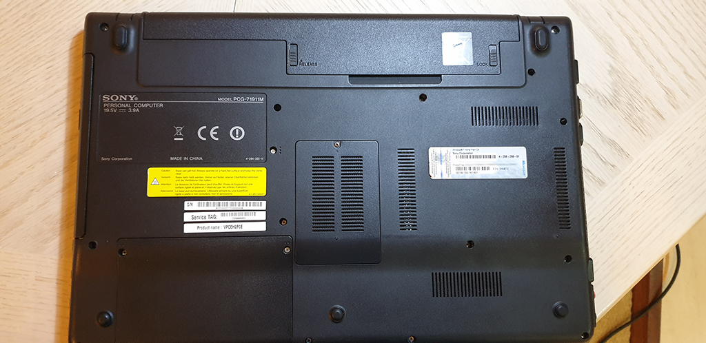
It is a Sony VAIO VPCEH2P0E laptop with an Intel Core i5-2430M processor (CPU) and an Intel HD Graphics 3000. I have already upgraded it with extra memory and a SSD drive and I thought it’s time for a CPU upgrade too.
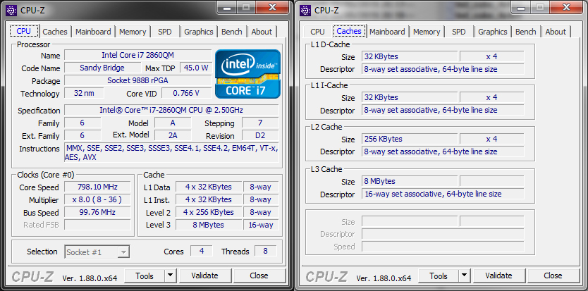
I used CPU-Z to find out more about the laptop. It revealed more details regarding the current CPU and the motherboard’s chipset.
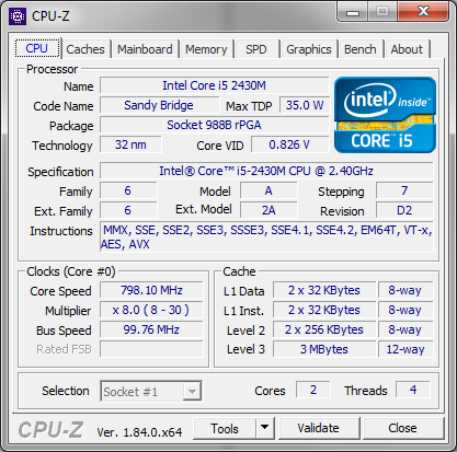
The dual core CPU has a base frequency of 2.40GHz which can go up to 3.00GHz when the turbo boost is active. Some important things for the upgrade are displayed too such as the Max TDP 35W and the Socket rPGA 988B (a.k.a Socket G2).
The ‘Mainboard’ tab contained the motherboard’s chipset (Southbridge) which is a Mobile Intel HM65 Express Chipset.
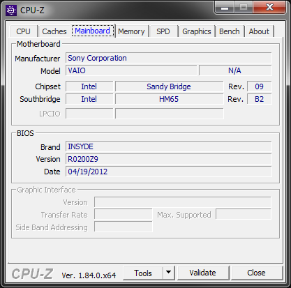
The BIOS version R0200Z9 is also presented on this page, which I used later to do some research.
Finding The Right CPU
I started my search based on the mainboard’s Intel HM65 chipset. The website www.cpu-upgrade.com gave me a nice list of the supported processors for my motherboard. I went through all the CPUs started from the bottom to check, which one of them has Socket G2 (rPGA 988B) packaging. After creating a list of the potential candidates and I checked their benchmarks on www.cpubenchmark.net, I picked the Intel i7-2860QM. Here is a comparison with my old CPU.
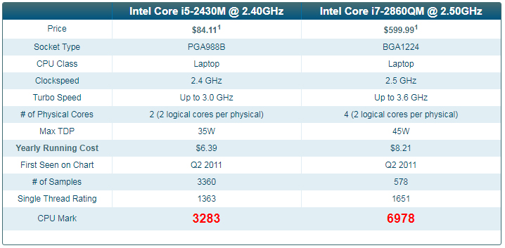
To me it looked a significant performance increase, over 112%! The socket types above are not matching, however Intel kindly supplies this chip with the suitable socket.
And will it work? It will physically fit. What about the BIOS support? And the increased TDP? After a long searching, I found on a forum that somebody successfully has replaced their i3-2330M CPU with this model having the identical socket and R0200Z9 BIOS version. The post looked genuine, so I thought I’ll give it a go too! Although the 45W TDP issue was still there to solve. It’s 10W higher and thus will produce more heat.
Disassembling The Sony VAIO VPCEH2P0E Laptop
It was time to disassemble the VAIO and have a look at it inside. I have never done this before after so many years of usage – apart of memory and SSD update.
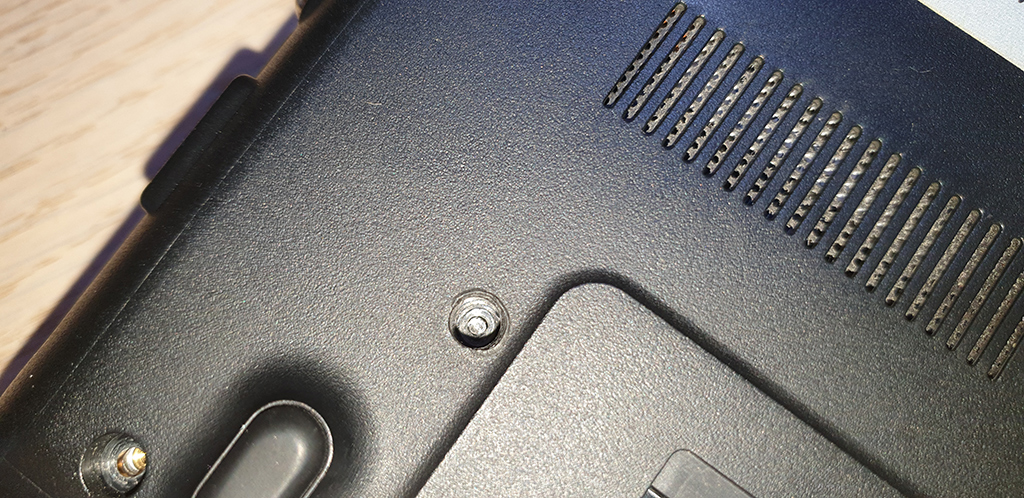
The reason why I hadn’t taken it apart was 3 stuck screws due to the plenty blue Loctite on their threads. I managed to stripped them.
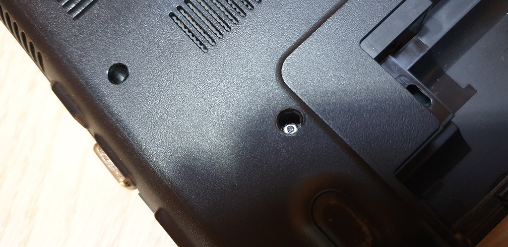
I needed to get a left-turn screw extractor drill bit which finally did the trick. The screws were so tough that the screw heads just broke off during the extraction.
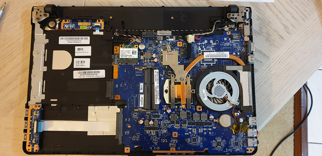
Finally I got it open!
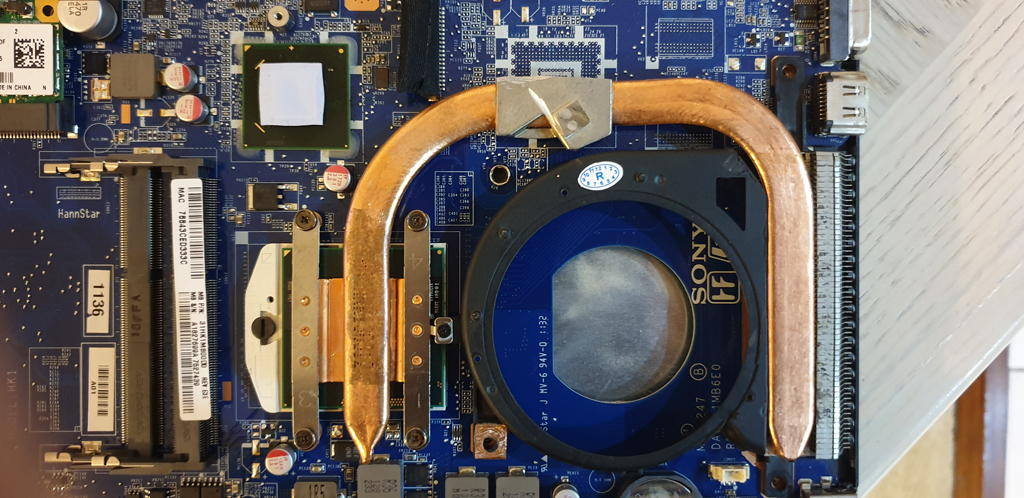
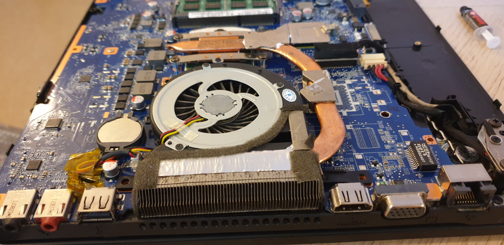
Solving The Cooling Problem
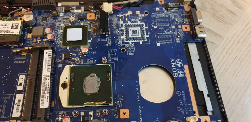
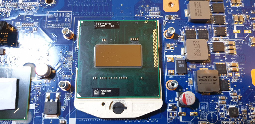
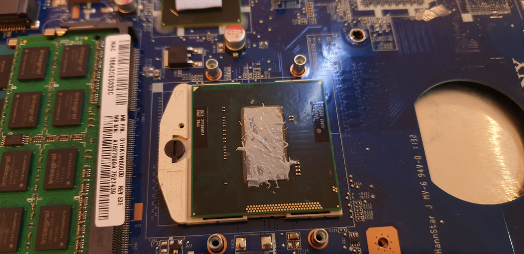
When I looked at the copper heat sink plate on the processor; it seemed to be too small. And the heat sink tube too.
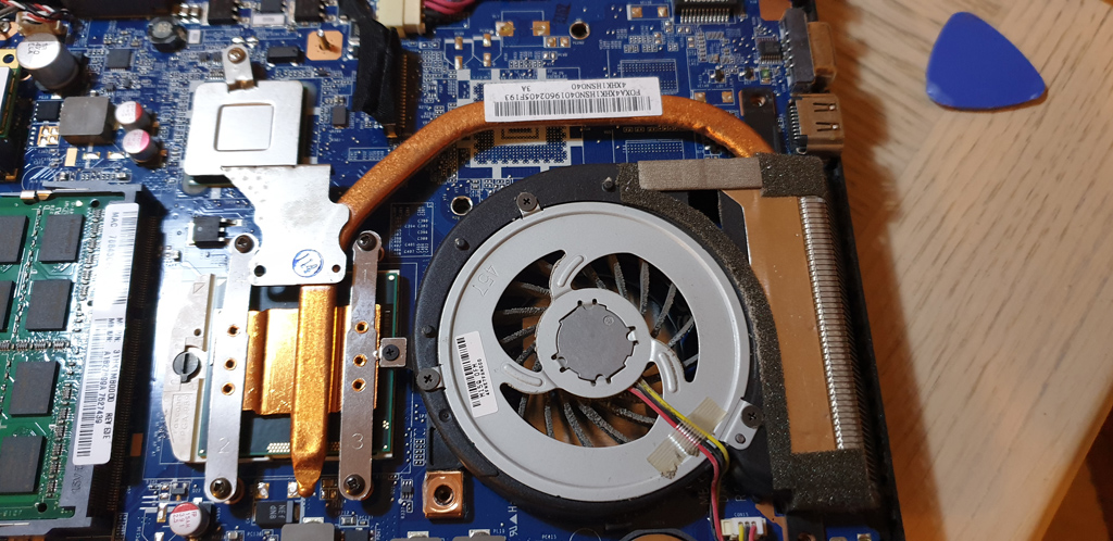
The width of the i7-2860QM’s core is way wider and the copper plate on mine was barely covering the core. And I knew my stock heatsink won’t be able to handle the 45W. Needed a new cooling system!
Finding A Suitable Heatsink
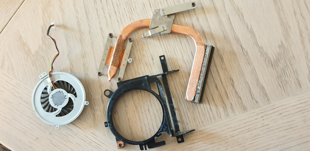
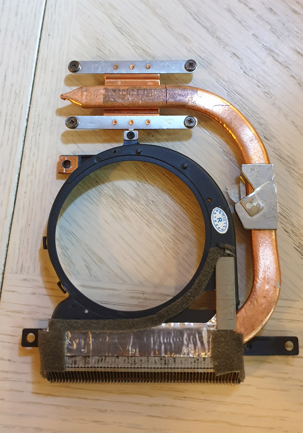
I went back online to look for an alternative cooling solution; only focusing on Sony VAIO parts. And after many hours/days of searching, I found a look alike one.
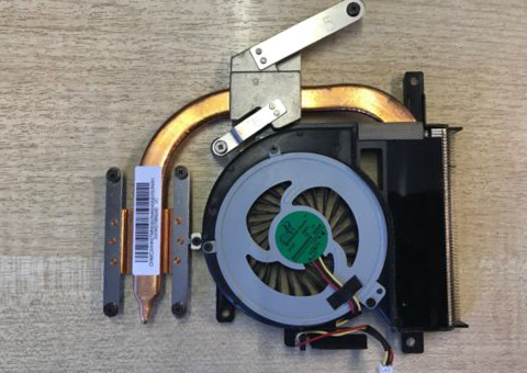
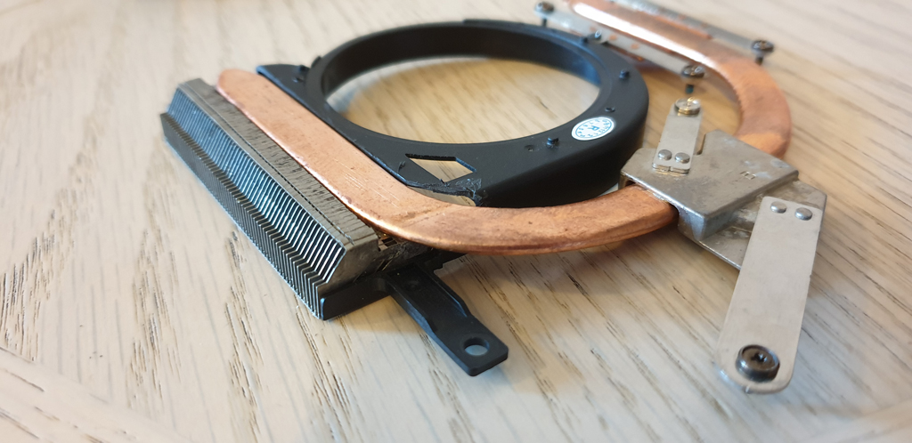
Same layout – by meaning the CPU is above the fan – and a thicker copper heat sink tube as well as a wider copper plate… Just as I wanted! This cooler is for Sony VAIO SVE151 series with an integrated GPU. It has to cool two processor cores. That’s why the tube is thicker. My laptop was not fitted with an onboard GPU but I could see the design markings for one. Did Sony use the same motherboard layout for the two VAIO models? I think so! Which means the heatsink and fan should work on mine with some modifications. So I ordered one!
While I was waiting for the heatsink, I order another one. The same as my original one to have it as a donor. I knew I had to do some modifications and I didn’t want to sacrifice the one in the laptop.
They arrived at the same time and I wanted to compare them straight away.
Quick Analysis
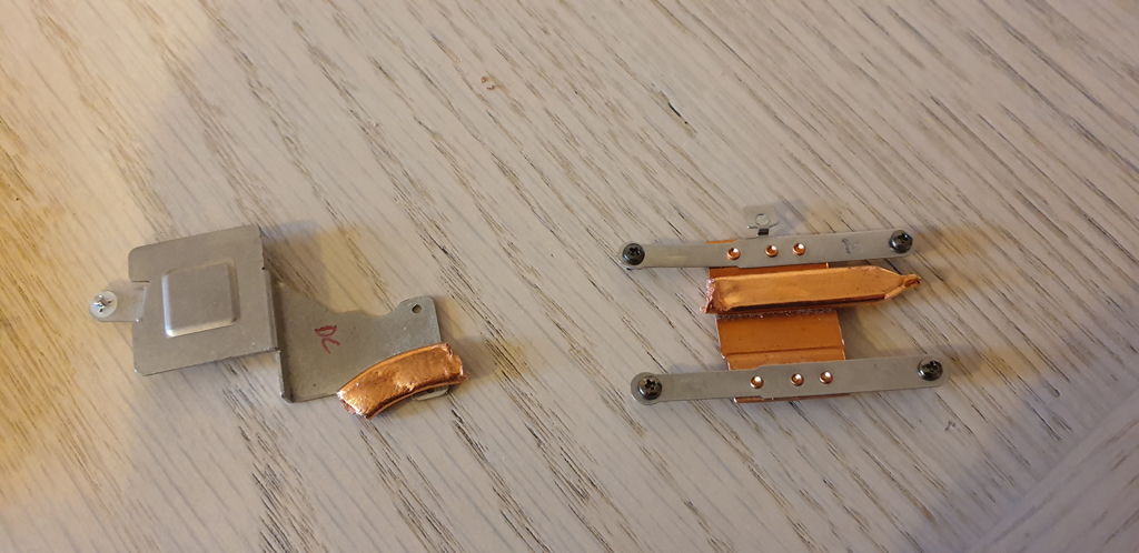
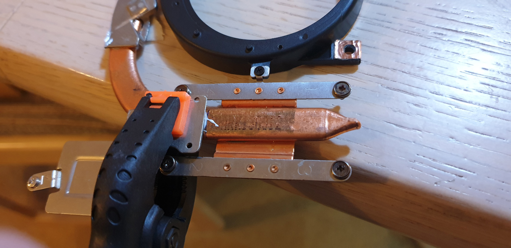
First I focused on the size of the copper plates.
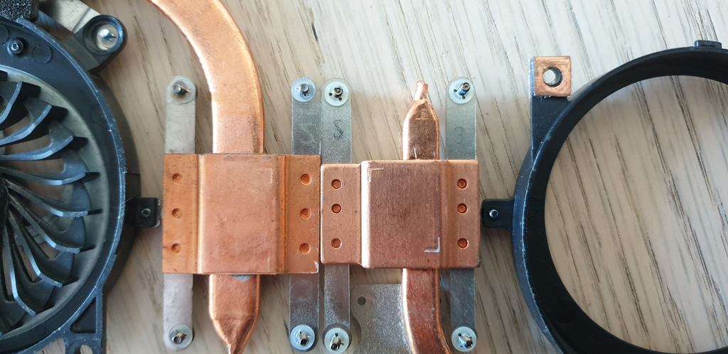
Just as I thought! On the left is the SV151’s copper plate and on the right is the same as mine. There is a significant width difference. But will it be wide enough?
I knew that the heatsink could work and the BIOS maybe compatible with the Intel i7-2860QM processor… I took my chances and ordered the CPU too.
Meanwhile, I started to plan the modification.
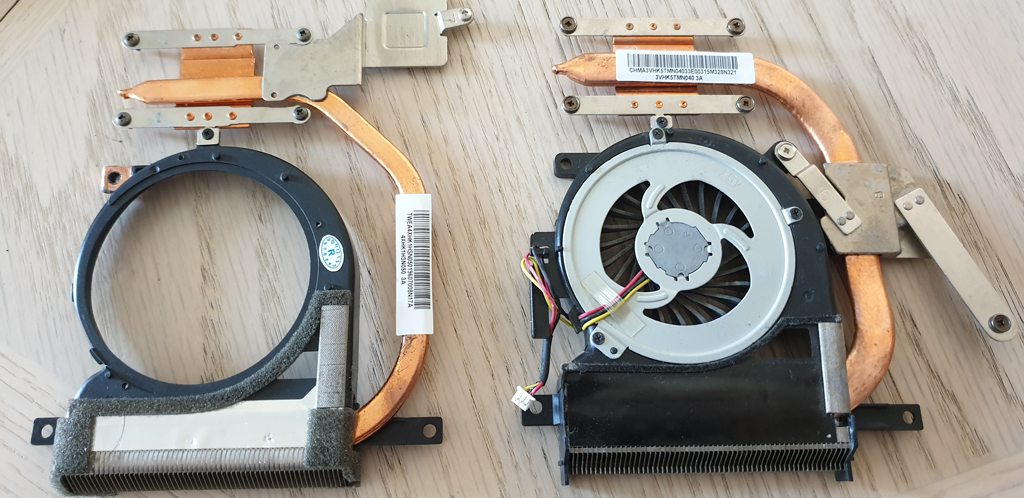
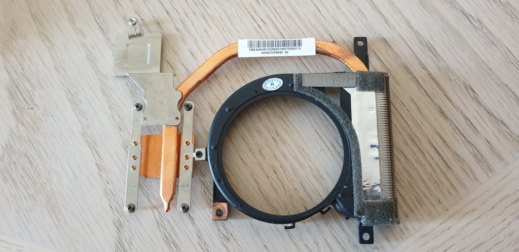
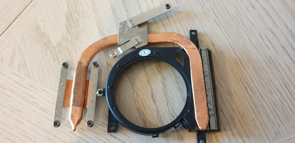
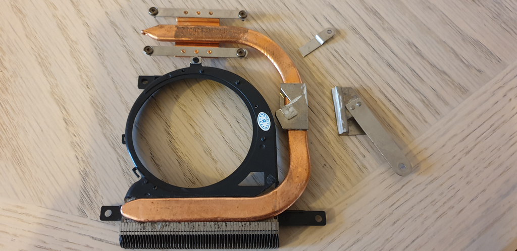
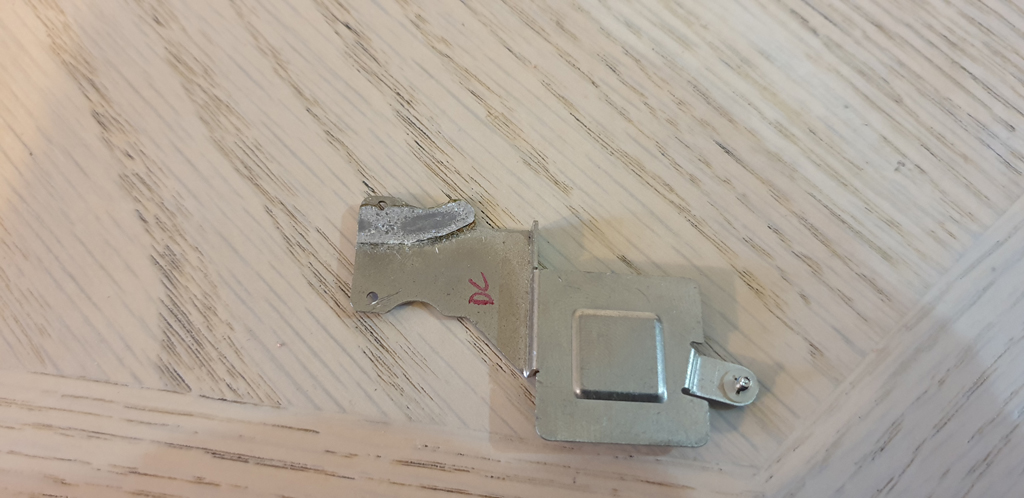
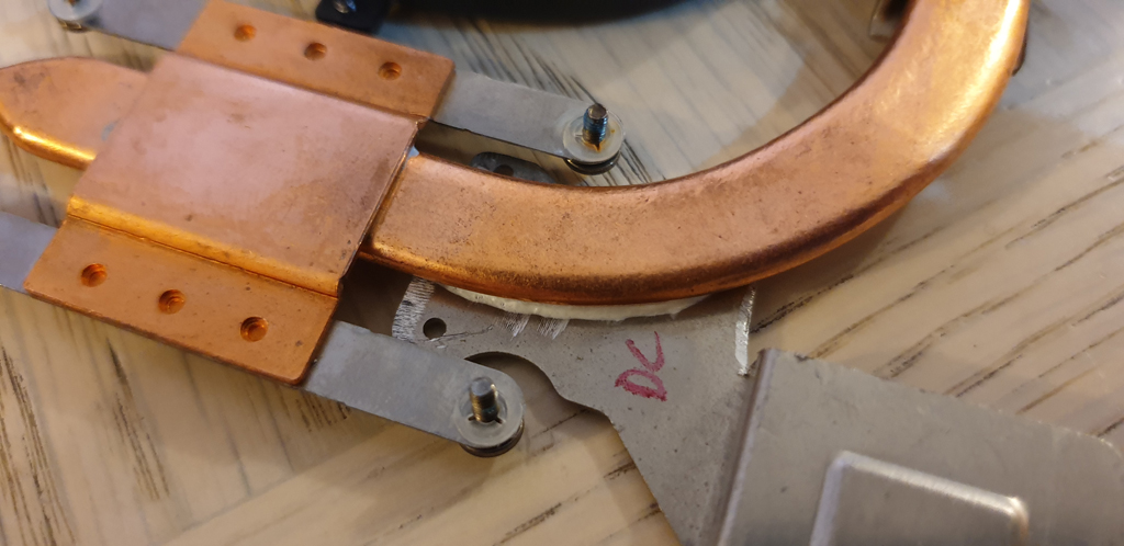
Looking at the two heatsinks, I could see some obvious differences between them. First, on mine (left) the additional metal plate which sits on the motherboard’s chipset; the other one didn’t have it. Second, the GPU’s heatsink (right) which mine didn’t have that.
At this point I couldn’t try it in the laptop as it was under continuous use, however I started the modification process.
Building A New Heatsink
Cutting The Plastic For The Heat Sink Tube
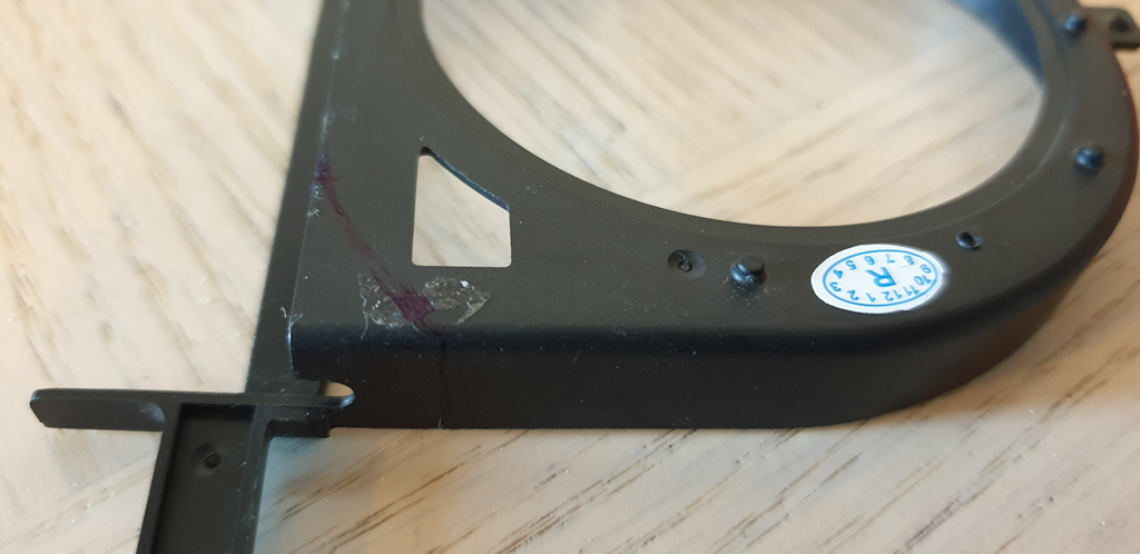
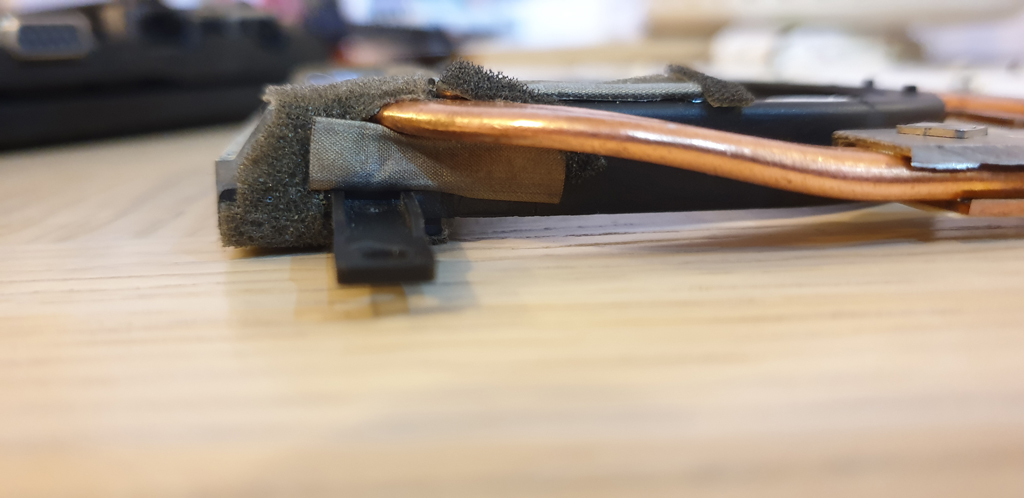
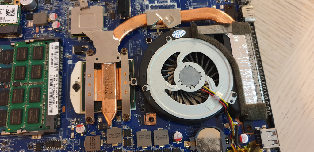
I noticed some additional differences on the plastic case which holds the fan. I decided to keep the original one as it would definitely fit. So I had to install the replacement grid and heat sink tube on it. I took both of them apart by carefully peeling the adhesive tape off from the top of the grid and around them.
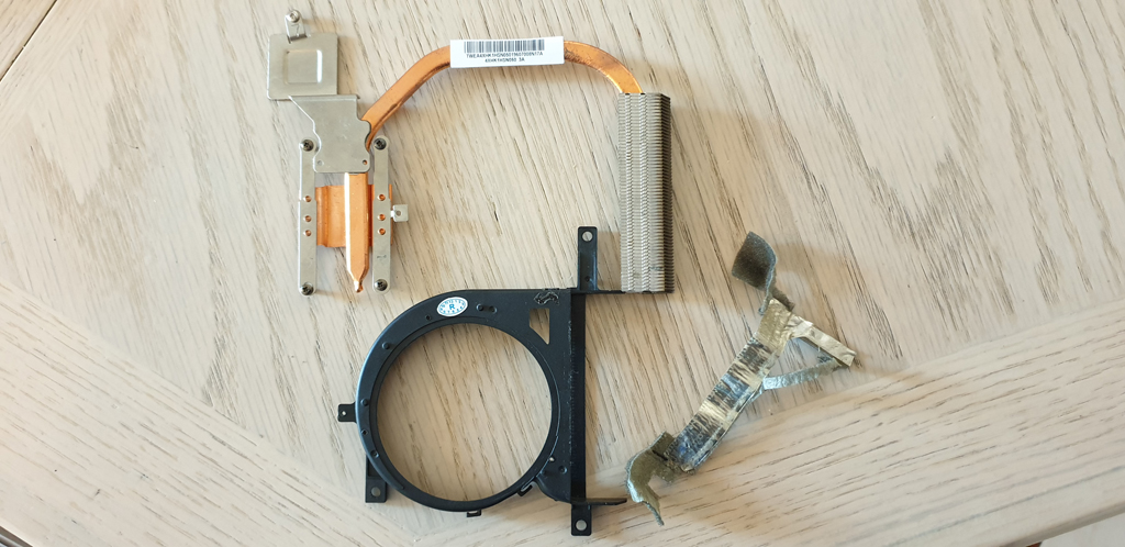
The grid with the copper heat sink tube nicely slipped out which was held by the adhesive tap only. I could have a better look at them. The grid with the thicker tube didn’t fit into the original fan socket. There was a slight curve which I had to cut out for it. The width was fine though.
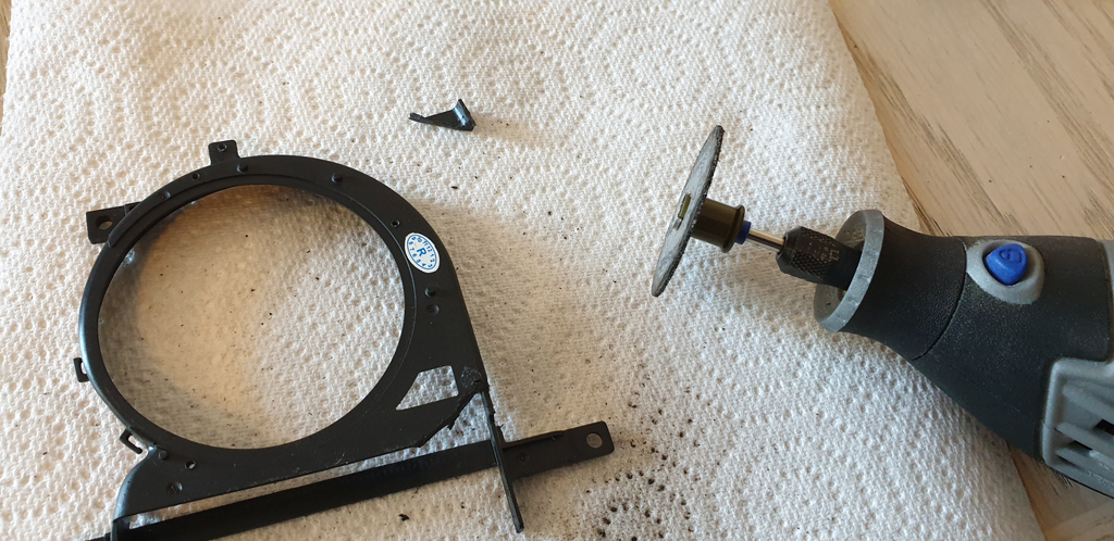
My Dremel tool was perfect for the task and I managed to cut out the corner without breaking the whole lot.
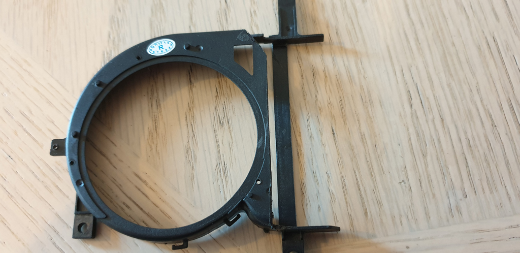
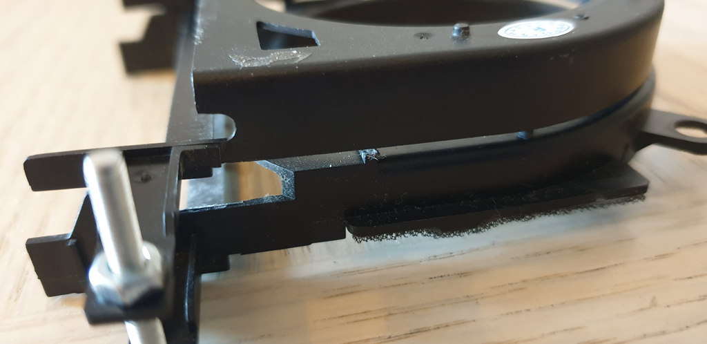
I also had to cut off a bit from the surrounding plastic of the grid; it was sticking out too far. After a few tries and cuts I manged to put the grid into the original fan case. It fit just as I imagined!
The screw hole on the top of the plastic aligned with the copper plate too.
Removing Part Of The GPU’s Heat Sink Plate
The next step was to get rid of that chunky GPU heat sink plate. Or at least some of it. I had to cut it very very carefully to not to damage the copper tube itself. I used my Dremel tool again.
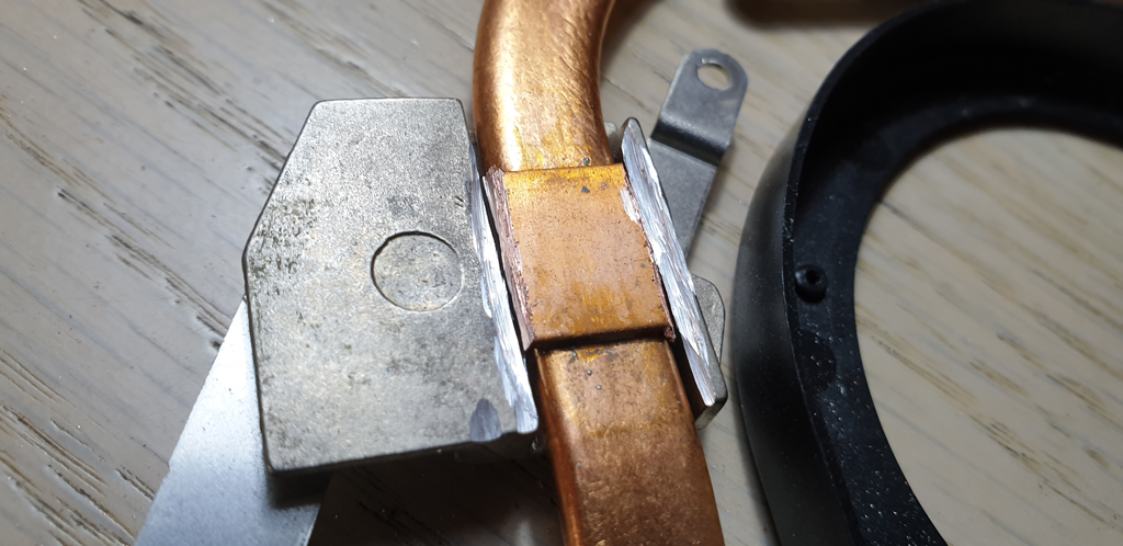
It was a slow and dirty process but I managed it! I had to wear eye protection due to some sparks and the all metal bits flying around.
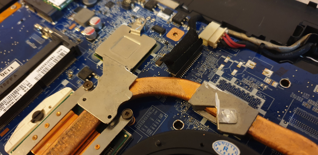
Removing The Motherboard Chipset Plate
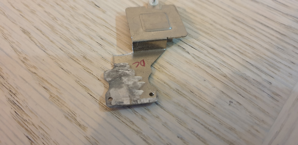
Transplanting the plate for the motherboard’s chipset was next. It was mounted with some heat transfer adhesive on the original copper tube. I just simply broke it off!
Then I cut a piece out for the wider copper tube and cleaned off the remaining adhesive.
First Try Of The Modified Heatsink
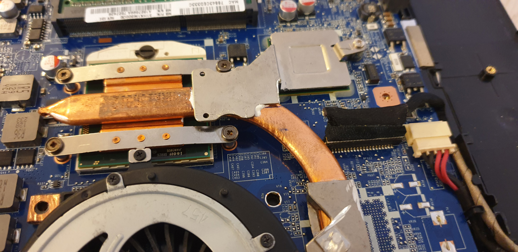
Finally it was time to try it out inside the laptop. I took the laptop apart again. This time it was easier as I didn’t tighten the screws. I removed the fan and heatsink and inserted my partly modified one.
Super! It did fit perfectly!
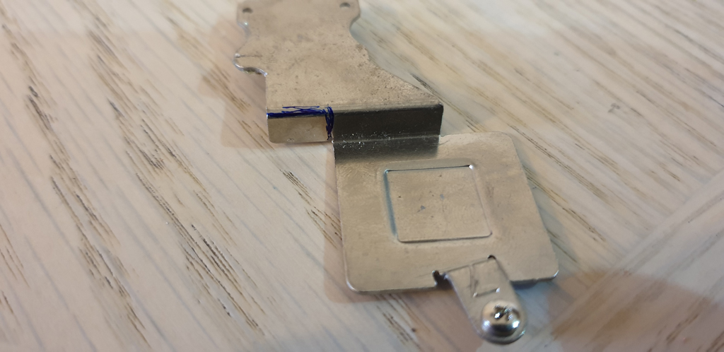
I softly tighten the four screws and positioned the heat sink plate for the Intel HM65 motherboard chipset. Then I tighten its screw and marked it on the copper tube.
At this point the grid was still loose in the black fan socket. So after cleaning the surfaces, I put the original adhesive tape back. Fortunately it still stuck very well.
Using Heat Transfer Adhesive
To permanently mount the previously prepared plate on the tube, I used some good quality heat transfer adhesive (Arctic Alumina).
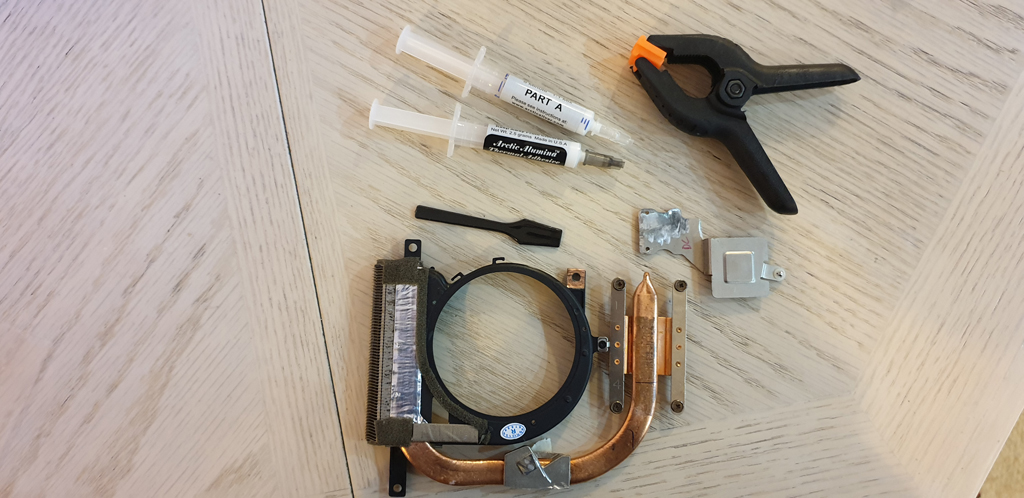
It’s a 2-part adhesive. Before applying it, I cleaned all the surfaces. I mixed a little together, not too much, and added to the heat sink plate. After positioning it I clamped it. Some excess adhesive squeezed out which was absolutely fine!

While I was waiting for the adhesive to set, I prepared the Intel Core i7-2860QM CPU.
After 2 hours of waiting the adhesive finally set.
The Assembling
As a final touch, I covered all the holes with some left over tapes for a better airflow.
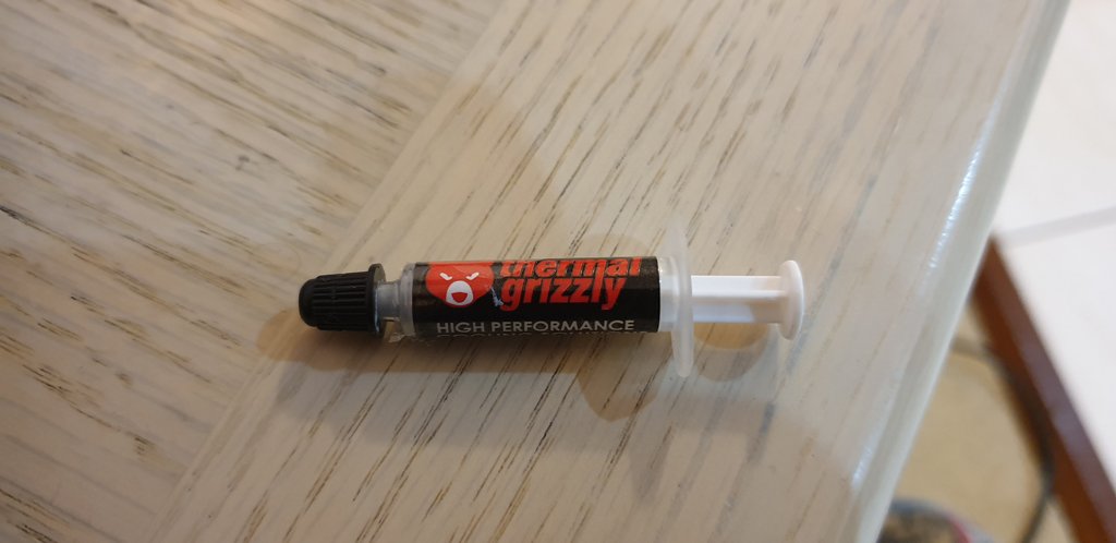
On the CPU I applied some high performance thermal grease for the best heat transfer between the processor’s core and the cooling plate. The motherboard’s chipset had a thermal pad on it which I didn’t touch.
It was time to place the heatsink inside the laptop. The first time when the replacement i7-2860QM CPU met with the modified heatsink. I had some doubts. Is the adhesive set in position? Is the CPU’s core properly covered with the copper plate? And then boom! Everything was aligned! I tightened all the screws and installed the fan.
Testing
I didn’t try out the Core i7 CPU in the laptop beforehand so I had no idea if it was going to work at all. I put the laptop back together and pressed the power button. IT BOOTED! However I couldn’t hear or feel the fan. It wasn’t spinning for about 2 minutes. Then suddenly it started. Huh!
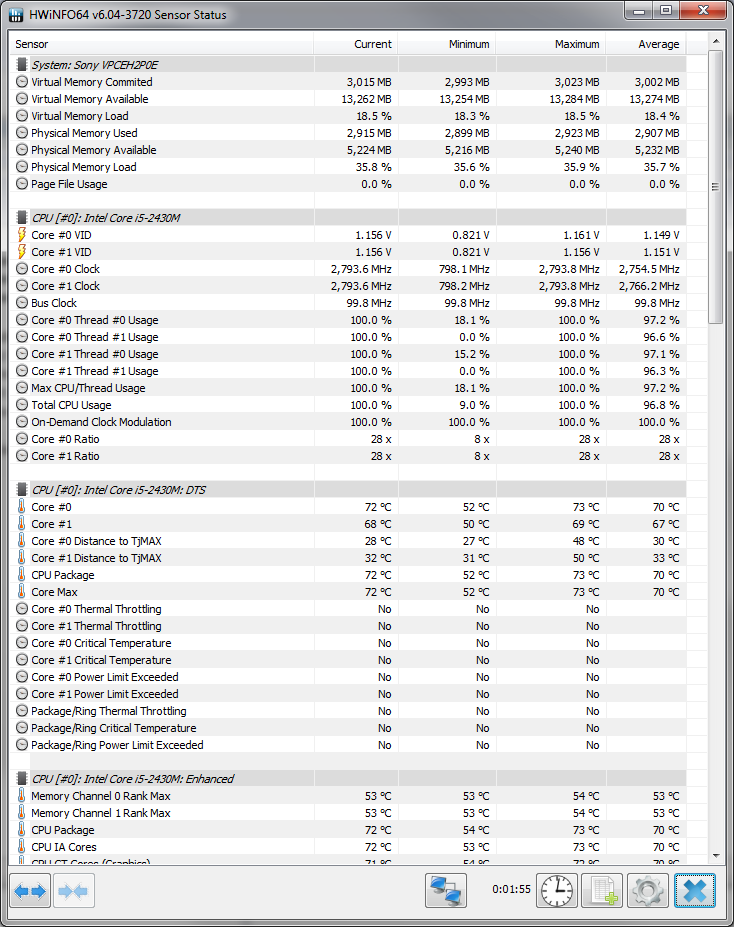
I was very curious how my DIY heatsink performs. So before I did some stress tests with the old Core i5 processor to see how high the temperature can get.
And then I performed the same with the i7 CPU.
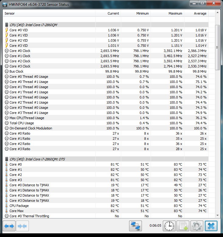
The temperature stopped at 83°C / 181°F and didn’t go higher! I’m very pleased with the final result. The whole system got noticeably faster!
For next, I’m thinking to upgrade the motherboard with an Intel HM76 chipset on it. I found that the Sony VAIO SVE151 range has a very similar board layout with integrated GPU and support for 3rd Intel i7 CPUs.
13 thoughts on “Sony VAIO i7-2860QM CPU & Heatsink Upgrade”
I bet the thing would still have worked with the old heatsink with minimal issues. CPUs rarely stay at 100% usage and if they do that for a while, they just throttle for a few seconds to cool off. I wonder (1) how much of the new core would have been left exposed with the old heat sink, and (2) what the stress test results would look like using the old heatsink and new CPU. Perhaps it would have throttled a little bit and that’s all. The design usually has room for some expansion. I did my own upgrade using the old heatsink from a 35 to 45W CPU and it works great although the old heat sink also covered the larger core on the new CPU. Throttling only happens every 30 seconds once the CPU has stayed at 100% for a few minutes and it doesn’t bother me. These things protect themselves. However yea I’d like to know the answers to the two questions.
Hello,
I first would like to thank you for all the detailled and revealing assembling information you share with us regarding the Vaio CPU upgrade. I want to do the exact same adaption as you did but I seem to get stuck in finding the i7 heatsink / cooling frame that you have used, or pragmatically said, one that has the same cooling conditions for CPU and GPU in the Vaio VPCEH3C4E edition I have. Could you perhaps tell me more about the one you got? In terms of a itemcode, which original motherboard it’s from or other relevant information so that I can continue following your adaption tutorial and make it work. Again, much regards for all the tutorial effort and explanation! You are a boss!
Hi,
Thank you for your comment. The part number of the replacement heatsink that I used is 3VHK5TMN040. Hope this will help!
An interesting example of a laptop upgrade. Maybe you still had to solder the video card? there was a place on the board for it and then there would be no need to change the board for Ivy Bridge. I have an Asus laptop HM65 chipset and BIOS version K53SD.208 (8/10/2012). Tell me, this BIOS supports 4 core processors (Core i7-2630QM,
Core i7-2670QM, Core i7-2720QM, Core i7-2760QM, Core i7-2820QM, Core i7-2860QM)?
According to this website http://valid.x86.fr/yxej78 the Asus K53SD.208 BIOS supports 4 core CPUs.
thanks for the help. Tell me, if a 4-core processor disables 1 core through Windows, will the processor and Windows start and work normally? Or is it better for 4-core processors to turn off turbo boost? I ask that my motherboard is designed for 2 nuclear processors and there may not be enough current or there will be overheating. Do you have a laptop with 4 cores and 8 threads? You can do such an experiment and test the processor in work with one disabled core (3 cores – 6 threads) and then with 4 cores, but without turbo boost. Interesting material for the article will be.
The laptop will get overheated if the replacement CPU has a higher TDP. Also the wattage of the power supply should be considered – more cores and higher TDP will increase the current draw. I believe disabling 1 core won’t affect Windows’ operation. I have InsydeH2O BIOS which doesn’t offer the option to turn on/off the CPU’s turbo boost by default. My BIOS has to be unlocked which I’m currently looking into.
one friend put instead of i5-2430m on 2 cores i7-2670qm on 4 cores and turned off turbo boost in it through the Windows power plan (set max 99% in cpu power). So his i7 in the stress test consumed only 37W. That is, like his former i5 (TDP = 35w). The performance of the laptop doubled, but the temperatures remained the same (max 75 * C). And the board does not experience overloads from a processor change, because with a turbo boost it consumes 45-52w TDP
Fantastic project and love all the pictures and writing, good job! I have a samsung chromebox with b940 celeron, but it can be upgraded as hm 65/g2 so I am hoping to try a 45w i7 2nd Gen. I am hopeful that the fact it is not a laptop (it has tiny vents at back and no screen ) that it will be cool enough. It has a copper heat sink and tube similarly. You can find pictures in a teardown of samsung chromebox 3 – it’s ssd msata is upgradeable and so too the ram to 16gb. It is necessary to put on new uefi BIOS
Good luck with your hm67 experiment!
Hi,
Yes, cooling is one of the challenges when you’re upgrading from 35W to 45W. The fan which I have is only 1.45W (5V * 0.29A) and it does the job. I think Chromebox 3 comes with a 2.5W (5V * 0.5A) fan which should be enough. The copper heatsink tube also needs to be wide enough to be able to transfer the heat to the fan. And the BIOS… I don’t know if Samsung was kind enough to support 4-core CPUs with their UEFI BIOS on the Chromebox 3. It’s worth to do a little bit of research. And another thing is to mention… the power supply. With a higher TDP the input will draw more amps. I didn’t have to change mine but I read that people had trouble with it after the upgrade – laptop wasn’t charging or kept turning off.
If the 45W i7 (4 core) won’t work out for you then you might want to try a 35W i7-2640M or i5-2540M. They are 2-core CPUs but still miles faster then the Celeron B940.
Thanks! (I ordered a similar heatsink sold under this fabrication part #,which looks equal to the one you ‘adapted’ for just $19.99 on ebay (https://www.ebay.com/vod/FetchOrderDetails?ViewPaymentStatus&purchaseOrderId=09-0671-489521) and am also expecting my to i7-i7-2820QM from Ebay to arrive with 2 weeks! I let you know how my journey went later this month!
Ok. I followed all the steps and made the heatsink fit. Unfortunately after installing the cpu and heatsink mine doesnt boot (yet after it did booted with the original i5 again, so nothing is broke fyi) The only difference on your situation is that I’m using a Intel Core i7-2820QM (https://m.nl.aliexpress.com/item/32999793150.html?trace=wwwdetail2mobilesitedetail&spm), but from the comparison info I got, it should work just like yours.. (https://www.cpu-world.com/Sockets/Socket%20G2%20(rPGA988B).html) Any ideas/tips what could be wrong?
Hmm… So it’s booting with the i5 but not with the i7. Have you tried the i7 in a different laptop with Intel HM65 chipset? Maybe faulty? Is your BIOS the latest?