Project Overview
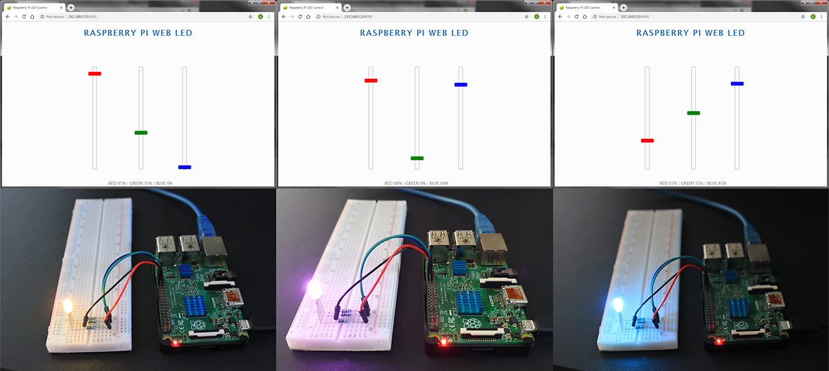
In this project I use a Raspberry Pi 2 Model B and connect a tri-colour (RGB) light emitting diode (LED) to its GPIO ports. Then I will set up the Pi to became a web server. The .jsp front page has 3 sliders where the user can adjust the brightness of the red, green and blue colours. All user actions are handled with AJAX and sent through WebSocket API (SockJS library) to Java’s servlet; here it gets processed and visualized. My goal is to achieve all this with Java (Spring Boot) and Pi4J library.
Supported Devices
I developed this tutorial on a Raspberry Pi 2 Model B, however it should work on the following models too (not tested).
- Raspberry Pi Model A+
- Raspberry Pi Model B+
- Raspberry Pi 2 Model B
- Raspberry Pi 3 Model B
- Raspberry Pi 3 Model B+
- Raspberry Pi Zero
- Raspberry Pi Zero W
Component List
List of components required for this project:
- 1 x Raspberry Pi 2 Model B
- 1 x 5mm RGB LED
- 3 x Resistors (see the values later)
- 1 x Solderless Breadboard
- 4 x Male to Female Jumper Wires
More information about the hardware setup will be detailed below.
Setting Up The Raspberry Pi
Operating System & Network Setup
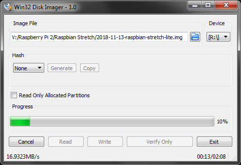
The operating system I choose was Raspbian Stretch Lite. The Lite means that the OS hasn’t got desktop interface – not required for this project – therefore it takes less space on the memory card. You can download it from the vendor’s website for free. The installation is fairly simple and straight forward. First you need to burn the image on a SD card. I used Win32 Disk Imager.
When it’s done, pop the card into the Pi and wait until the operating system is booted up. The default username is pi and the password is raspberry. Before continue, it is recommended that you update the operating system.
$ sudo apt-get update
$ sudo apt-get upgrade
This could take a few minutes.
I was planning to use the Raspberry Pi as a web server. Therefore it should have its own static IP address. The system default is dynamic, so every time the OS reboots we could end up with a different IP. You can use the IP address which was given by your DHCP server and set it as a static address. This will avoid any conflict on your network. You can check the network configuration with the ifconfig command.
$ ifconfig
Result:
eth0: flags=4163<UP,BROADCAST,RUNNING,MULTICAST>	mtu	1500
		inet 192.168.0.10	netmask 255.255.255.0	broadcast 192.168.0.255
		inet6 fe80::2be9:8f1f:6aee:e9a8	prefixlen 64	scopied 0x20<link>
		ether b8:27:eb:a4:12:d6	txqueuelen 1000	(Ethernet)
		RX packets 89399	bytes 131734141 (125.6 MiB)
		RX errors 0	dropped 0	overruns 0	frame 0
		TX packets 25492	bytes 2033000 (1.9 MiB)
		TX errors 0	dropped 0	overruns 0	carrier 0	collision 0
On my network the dynamic IP address was 192.168.0.10. Later I will use this as a reference address. You can find yours after the inet label. Now we can set the IP as static by editing /etc/dhcpcd.conf.
$ nano /etc/dhcpcd.conf
Add the following lines at the end of the file:
interface eth0

static ip_address=192.168.0.10/24
static routers=192.168.0.1
static domain_name_servers=8.8.8.8 8.8.4.4
static routers=192.168.0.1 is my gateway’s (router’s) IP address. static domain_name_servers=8.8.8.8 8.8.4.4 represents the DNS servers. They are Google’s Public DNS servers.
As I’m using a lite version of the OS; there is no need for a screen and keyboard to be connected to the Pi. Everything can be done via SSH which will leave us with only 2 cables connected to it; power supply and network. SSH server is disabled by default but you can enable it from the system’s configuration.
$ sudo raspi-config
- Here select
Interfacing Options - Navigate to and select
SSH - Choose
Yes - Select
Ok - select
Finish
It’s time to reboot to see if it worked.
$ sudo reboot
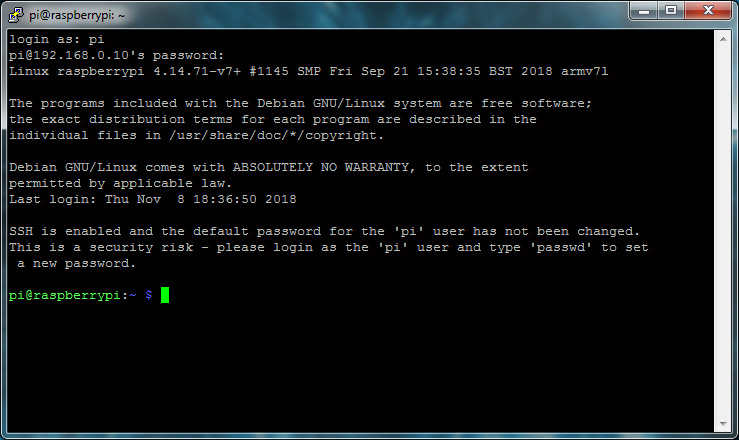
You can connect now to the Raspberry Pi via SSH by using a client software. My favourite one is PuTTY. For the Host Name use the static IP on port 22. The credentials to login are the same.
Installing Required Packages
During the development, you will need to access to the Raspberry Pi via FTP to be able to upload files to it.
Installing the FTP server:
$ sudo apt-get install proftpd
After successful installation, the FTP server should be up and running. It can be reached via the Pi’s static IP on port 21. The login credentials are the same again.
Now at this point, we need to install 3 additional packages too.
Java JDK
For this project it is essential to have Java JDK installed and properly configured on the system. As a start we can install Oracle Java JDK.
$ sudo apt-get install oracle-java8-jdk
JAVA_HOME environmental variable must be added to the global PATH so all Java executable files can be reached from any directories. We need to edit ~/.bashrc and add the following lines at the end of the file.
$ nano ~/.bashrc
export JAVA_HOME="/usr/lib/jvm/jdk-8-oracle-arm32-vfp-hflt"
export PATH=$PATH:$JAVA_HOME/bin
JAVA_HOME is the name of the environmental variable. This is used by applications as the symbolic link to Java’s installation directory. Declared every time when the system boots up. During the boot process $PATH is extended with $JAVA_HOME/bin. The /bin directory contains the executable files which becomes global and the user can access it form any locations.
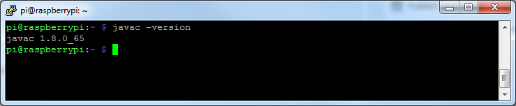
After a reboot you can check if the setup us correct by checking Java compiler’s version.
$ javac -version
WiringPi
WiringPi is a necessary package for Pi4J Java library. Before installing it, we need to install GIT on the Raspberry Pi because the package will be pulled from GitHub.
$ sudo apt-get install git-core
Now the WiringPi. Please not the capital ‘P’ in the address.
$ cd ~
$ git clone git://git.drogon.net/wiringPi
$ cd ~/wiringPi
$ ./build
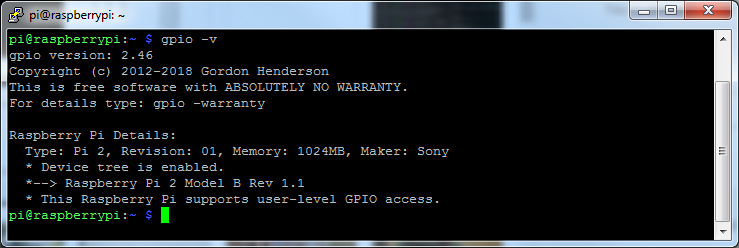
This is how you can check if the installation was successful.
$ gpio -v
Maven
Maven is a build automation software. It handles all the required packages (dependencies) and put all the source files together. Very efficient tool. The compile process should happen on the Raspberry Pi. Therefore Maven needs to be installed on it too.
On the Pi, download and extract the source code.
$ wget http://apache.mirrors.pair.com/maven/maven-3/3.6.0/binaries/apache-maven-3.6.0-bin.tar.gz
$ tar -xzvf apache-maven-3.6.0-bin.tar.gz
$ rm apache-maven-3.6.0-bin.tar.gz
Move the extracted directory to an appropriate location.
$ sudo mv apache-maven-3.6.0 /opt/
Maven can be run from anywhere by setting an environmental variable to its location. We can create this shell script which will launch during the boot process…
$ sudo nano /etc/profile.d/maven.sh
…and add the following lines.
#!/bin/bash
export M2_HOME=/opt/apache-maven-3.6.0
export PATH=$PATH:$M2_HOME/bin
Log out from the Raspberrey Pi and back so you can test the script.
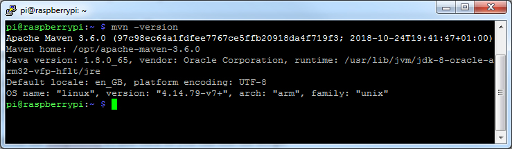
$ mvn -version
If you have it working, then you should see Maven’s version number.
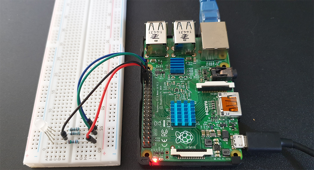
Setting Up The Pi’s Hardware
For this tutorial, we are using the WiringPi/Pi4J library. It has a different numbering for the GPIO pins. To find out more about the pin numbering, visit WiringPi’s website.
About The Components
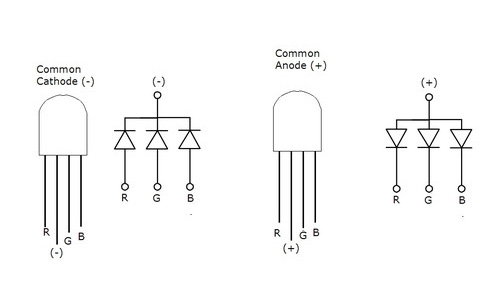
RGB LEDs have four connections; three of them for the colours and one is the ground. The LED I chose is a 5mm Diffused RGB LED with common cathode connection. Common anode LEDs will work too, however the wiring differ to the other type.
Instead of diffused LED, clear ones can be used as well. The diffused LED’s lens look cloudy which helps the light to diffuse more evenly than the clear lens.
The LED requires 3 resistors which values depend on the manufacturer. This can be calculated from the specifications of the LED. The required values are the supply voltage (V), forward voltage (V) and the forward current (mA). The supply voltage is the same as the Raspberry Pi’s output which is 5V. Forward voltage and current are the values specified by the manufacturer and various to each makes. Also with the RGB LEDs, the red connection has a lower value than the green and the blue. The one I have has the following values:
- Red: 1.8V / 20mA (0.02A)
- Green: 3.1V / 20mA (0.02A)
- Blue: 3.1V / 20mA (0.02A)
Use the formula below to determinate the required resistors.
R = (Vs – Vf) / If
- Vs: Supply voltage (V)
- Vf: Forward voltage (V)
- If: Forward current (A)
Based on this my resistor values are:
- Red: (5V – 1.8V) / 0.02A = 160Ω
- Green: (5V – 3.1V) / 0.02A = 95Ω ≈ 100Ω
- Blue: (5V – 3.1V) / 0.02A = 95Ω ≈ 100Ω
Wiring
As mentioned above, there are 2 different type of RGB LEDs; common cathode and common anode. The wiring is really similar. The only difference is that the common cathode’s (-) second pin is connected to the Pi’s ground and where the common anode (+) version is connected to the 5V power pin. In my tutorial I’m using a common cathode LED.
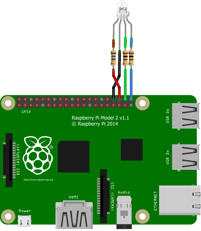
The 3 RGB pins are wired to the Pi’s GPIO connectors. With WiringPi/Pi4J library the GPIO pin numbering is not the same as the manufacturer defines. We are using these numbers to set pins for the LED connections.
| LED Pin | Name (WiringPi/Pi4J) | Physical Pin |
| RED | GPIO 27 | 36 |
| GROUND | GND | 34 |
| GREEN | GPIO 28 | 38 |
| BLUE | GPIO 29 | 40 |
You can pick different pins. You just need to modify the GPIO numbers in the source code accordingly.
For detailed pin layouts visit Pi4J website.
About The Application
To be able to control the RGB Led connected to the Raspberry Pi we will need to create some sort of application. I decided to use Java Spring Boot with embedded Tomcat Servlet. The advantage of this, is that it doesn’t require any third party server installed on the host (Raspberry Pi). Everything is packed into one WAR file (Java Classes, servlet, application settings,…). Pi4J library with WiringPi are responsible to control the Pi’s GPIOs. It uses software PWM (Pulse Width Modulation) to adjust the brightness of the colours of the RGB Led. The user input on the front web page is handled by the WebSocket communication protocol. It is a two-way channel between server and client. On the client side SockJS, a Javasript library is implemented. The final application will only contain a .war file and by launching it on the Pi, the Tomcat servlet will be initialized.
Creating The Java Project With Maven
I presume that you have Java JDK 8 and Maven installed with the required environment variables on the developing machine. For this tutorial I used Eclipse IDE for Java with included Maven packages. Still an additional plugin from Eclipse Marketplace is required:
- Eclipse Java EE Developer Tools 3.11 (by The Eclipse Foundation)
Template Setup
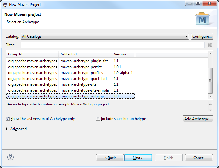
Create a new Maven Project and for archetype select maven-archetype-webapp.
On the next window, complete the required project details.
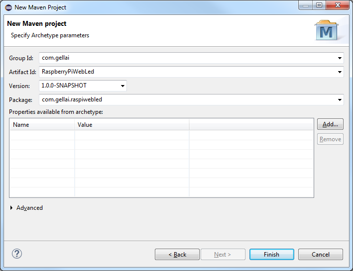
This will create a webapp template for the Maven project. At this point Eclipse will show some errors. You can ignore them for now.
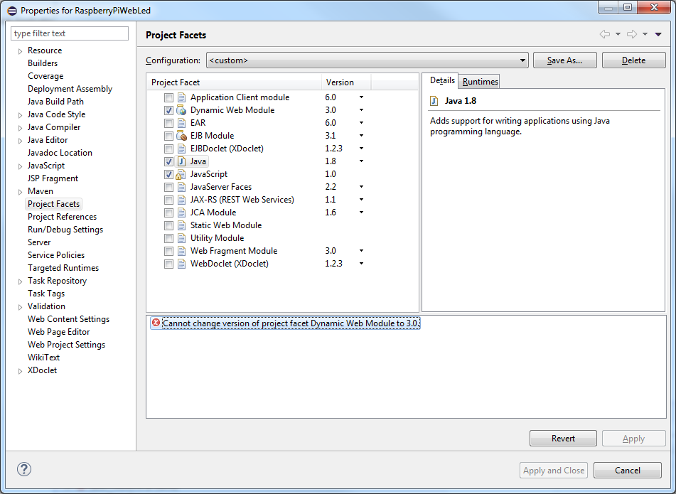
It is important that the project has the correct settings. First we need to change some properties. Within the project’s properties – when you try to set the Dynamic Web Module version to 3.0 and Java to 1.8 – Eclipse may give you an error and the changes won’t get saved.
To bypass this you need to edit the org.eclipse.wst.common.project.facet.core.xml file directly. It can be found in the project folder under .settings. The file should look like this:
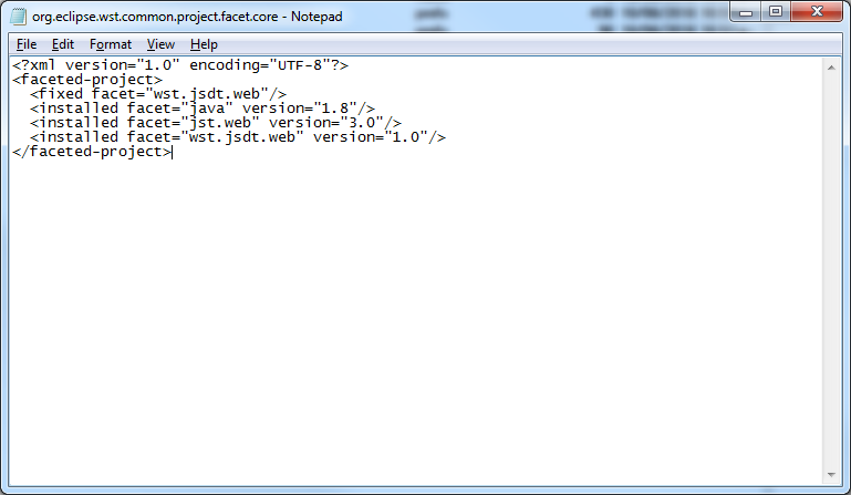
After saving the file Refresh the project.
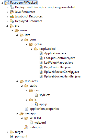
Now we are ready to create the project’s folder and file structures, which at the end will look like this:
Spring Boot with Embedded Tomcat Servlet
First edit the pom.xml (Project Object Model) file. It contains the configuration details of the Maven project.
<project xmlns="http://maven.apache.org/POM/4.0.0"
    xmlns:xsi="http://www.w3.org/2001/XMLSchema-instance"
    xsi:schemaLocation="http://maven.apache.org/POM/4.0.0 http://maven.apache.org/maven-v4_0_0.xsd">
    <modelVersion>4.0.0</modelVersion>

    <groupId>com.gellai</groupId>
    <artifactId>RaspberryPiWebLed</artifactId>
    <packaging>war</packaging>
    <version>1.0.0-SNAPSHOT</version>
    <name>Raspberry Pi Web Server - RGB LED Control</name>
    <url>https://gellai.com</url>

    <parent>
        <groupId>org.springframework.boot</groupId>
        <artifactId>spring-boot-starter-parent</artifactId>
        <version>2.0.3.RELEASE</version>
    </parent>

    <properties>
        <java.version>1.8</java.version>
    </properties>

    <dependencies>
        <!-- JSTL for JSP pages -->
        <dependency>
            <groupId>javax.servlet</groupId>
            <artifactId>jstl</artifactId>
        </dependency>

        <!-- Starter for building Web (Tomcat) -->
        <dependency>
            <groupId>org.springframework.boot</groupId>
            <artifactId>spring-boot-starter-web</artifactId>
        </dependency>

        <!-- Starter for using Tomcat as the embedded servlet container -->
        <dependency>
            <groupId>org.springframework.boot</groupId>
            <artifactId>spring-boot-starter-tomcat</artifactId>
            <scope>provided</scope>
        </dependency>

        <!-- Core Tomcat implementation -->
        <dependency>
            <groupId>org.apache.tomcat.embed</groupId>
            <artifactId>tomcat-embed-jasper</artifactId>
            <scope>provided</scope>
        </dependency>

        <!-- WebSocket application -->
        <dependency>
            <groupId>org.springframework.boot</groupId>
            <artifactId>spring-boot-starter-websocket</artifactId>
        </dependency>

        <!-- Raspbery Pi GPIO repository. 1.2-SNAPSHOT provides support for BMC8325 -->
        <dependency>
            <groupId>com.pi4j</groupId>
            <artifactId>pi4j-core</artifactId>
            <version>1.2-SNAPSHOT</version>
        </dependency>
    </dependencies>

    <!-- Alternative repository source required for com.pi4j.pi4j-core-1.2-SNAPSOT -->
    <repositories>
        <repository>
            <id>oss-sonatype</id>
            <name>oss-sonatype</name>
            <url>https://oss.sonatype.org/content/repositories/snapshots/</url>
            <snapshots>
                <enabled>true</enabled>
            </snapshots>
        </repository>
    </repositories>

    <build>
        <!-- Will create raspiwebled.war -->
        <finalName>raspiwebled</finalName>
        <plugins>
            <plugin>
                <groupId>org.springframework.boot</groupId>
                <artifactId>spring-boot-maven-plugin</artifactId>
            </plugin>

            <plugin>
                <groupId>org.apache.maven.plugins</groupId>
                <artifactId>maven-dependency-plugin</artifactId>
            </plugin>
        </plugins>
    </build>
</project>
Create the java folder within src/main/. This folder is not created with maven-archetype-webapp template. Once it’s done, right click on the new java folder and create a new Package.

Now right click on the newly created package com.gellai.raspiwebled and add a Class. I named it Application.java. This java class will contain our main method and will initialize the Spring Boot Application.
package com.gellai.raspiwebled;

import org.springframework.boot.SpringApplication;
import org.springframework.boot.autoconfigure.SpringBootApplication;
import org.springframework.boot.builder.SpringApplicationBuilder;
import org.springframework.boot.web.servlet.support.SpringBootServletInitializer;

@SpringBootApplication
public class Application extends SpringBootServletInitializer
{
    @Override
    protected SpringApplicationBuilder configure(SpringApplicationBuilder application) {
        return application.sources(Application.class);
    }

    public static void main(String[] args) throws Exception {
        SpringApplication.run(Application.class, args);
    }
}
Also we add the PageController.java which is a controller to map HTTP requests. Here we only deal with the index request.
package com.gellai.raspiwebled;

import org.springframework.stereotype.Controller;
import org.springframework.web.bind.annotation.RequestMapping;

@Controller
public class PageController
{
    @RequestMapping("/")
    public String index() {
        return "index";
    }
}
Also we have to tell the application about the source folder and the extension of the web page file(s). Let’s use the base folder which is src/main/webapp/ and the general JavaServer Page extension .jsp. We create a file and name it application.properties in src/main/resources/.
server.port = 8080

spring.mvc.view.prefix: /
spring.mvc.view.suffix: .jsp
I added server.port = 8080 which defines the access port of the running web application. This is optional and you can choose any other ports. The default is port 80.
To make index.jsp the welcome page, we edit the web.xml within src/main/webapp/WEB-INF/. The index.jsp was created with the template in src/main/webapp/.
<?xml version="1.0" encoding="UTF-8"?>
<web-app xmlns:xsi="http://www.w3.org/2001/XMLSchema-instance"
    xmlns="http://xmlns.jcp.org/xml/ns/javaee"
    xsi:schemaLocation="http://xmlns.jcp.org/xml/ns/javaee http://xmlns.jcp.org/xml/ns/javaee/web-app_3_1.xsd"
    id="WebApp_ID" version="3.1">

    <display-name>Raspberry Pi Web Server RGB LED Control</display-name>
    <welcome-file-list>
        <welcome-file>index.jsp</welcome-file>
    </welcome-file-list>
</web-app>
You can now right click on the project and Maven then Update Project… or Alt + F5. This should clean all your error messages.
At this point you should have a working web application which you can test.
- Connect to the Raspberry Pi via FTP using your favourite client software
- Copy the whole Maven project’s folder on it
- Login to the Raspberry Pi via SSH
In SSH navigate to the project’s folder and build the package with this Maven command:
$ cd RaspberryPiWebLed/
$ mvn package
This will automatically download and compile the application on the Raspberry Pi. When it’s done navigate to the target/ directory. There, you should see the newly created raspiwebled.war file. You can run it to see if everything is working.
$ cd traget/
$ java -jar raspiwebled.war
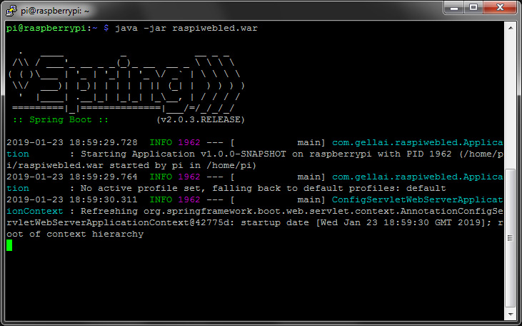
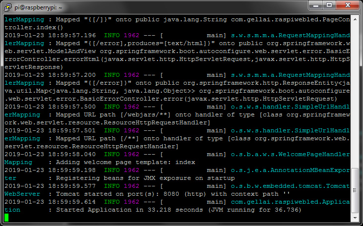
When the application is fully loaded the message “Started Application in...” will be displayed.
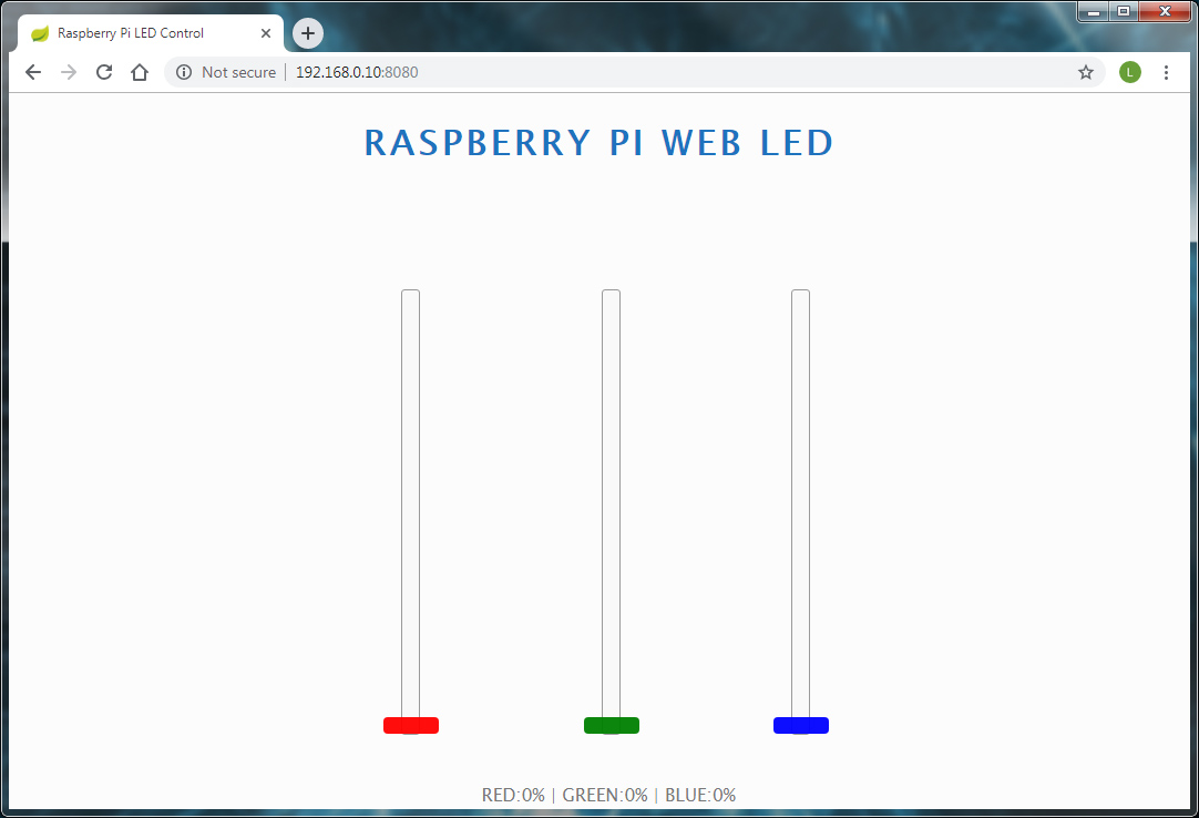
You can open a browser and navigate to the Pi’s IP address, which is in my case is: http://192.168.0.10:8080

The “Hello World!” message indicates that your Tomcat servlet is running.
Extending Java Servlet With WebSocket
To communicate with the LEDs in real time via the web browser we need to add WebSocket to the Servlet. It helps to establish a tunnel between the front page and Pi4J library.
Let’s create the WebSocket’s configuration file RpiWebSocketConfig.java.
package com.gellai.raspiwebled;

import org.springframework.context.annotation.Bean;
import org.springframework.context.annotation.Configuration;
import org.springframework.web.socket.WebSocketHandler;
import org.springframework.web.socket.config.annotation.EnableWebSocket;
import org.springframework.web.socket.config.annotation.WebSocketConfigurer;
import org.springframework.web.socket.config.annotation.WebSocketHandlerRegistry;

@Configuration
@EnableWebSocket
public class RpiWebSocketConfig implements WebSocketConfigurer
{
    @Override
    public void registerWebSocketHandlers(WebSocketHandlerRegistry registry) {
        registry.addHandler(rpiWebSocketHandler(), "/gpio-websocket")
                .withSockJS();
    }

    @Bean
    public WebSocketHandler rpiWebSocketHandler() {
        return new RpiWebSocketHandler();
    }
}
In this script I configured the endpoint with the URI "/gpio-websocket". On the front end the connection is established by SockJS which is a Javascript library and a WebSocket client. It also provides intelligent fallback options for older browsers. The class of the WebSocket handler is also instantiated here within a new method annotated as @Bean.
We can create the handler class RpiWebSocketHandler.java – just as declared above.
package com.gellai.raspiwebled;

import org.springframework.web.socket.CloseStatus;
import org.springframework.web.socket.TextMessage;
import org.springframework.web.socket.WebSocketSession;
import org.springframework.web.socket.handler.TextWebSocketHandler;

public class RpiWebSocketHandler extends TextWebSocketHandler
{
    private static LedGpioController ledGpioController = new LedGpioController();

    @Override
    public void afterConnectionEstablished(WebSocketSession session)
            throws Exception {

//      System.out.println("Session ID: " + session.getId());
        ledGpioController.getLedHtmlSlider(session);
    }

    @Override
    public void handleTextMessage(WebSocketSession session, TextMessage message)
            throws Exception {

        ledGpioController.setLedsPwm(message.getPayload(), session);
    }

    @Override
    public void handleTransportError(WebSocketSession session, Throwable exception)
            throws Exception {

        session.close(CloseStatus.SERVER_ERROR);
        System.out.println("Connection error with session '" + session.getId() + "': " + exception);
    }
}
The handler as its name suggests handles the connection, incoming messages, packets and errors. After the LED’s GPIO controller class is instantiated and the connection is established and opened, the WebSocket session is set.
The next class is about to control the LED via the Pi’s GPIO by implementing the Pi4J library. LedGpioController.java This is where the actual colour change is happening. The brightness of a colour is set with software PWM. If you wish to change the GPIO pins on the Pi, you can do it here.
package com.gellai.raspiwebled;

import java.util.HashMap;
import java.util.Map;

import org.springframework.web.socket.TextMessage;
import org.springframework.web.socket.WebSocketSession;

import com.fasterxml.jackson.databind.ObjectMapper;
import com.pi4j.io.gpio.GpioController;
import com.pi4j.io.gpio.GpioFactory;
import com.pi4j.io.gpio.GpioPinPwmOutput;
import com.pi4j.io.gpio.Pin;
import com.pi4j.io.gpio.RaspiPin;

public class LedGpioController
{
    private static final Pin RED_LED_PIN   = RaspiPin.GPIO_27; // Physical Pin 36 - Pi4J/WiringPi 27 - RED
    private static final Pin GREEN_LED_PIN = RaspiPin.GPIO_28; // Physical Pin 38 - Pi4J/WiringPi 28 - GREEN
    private static final Pin BLUE_LED_PIN  = RaspiPin.GPIO_29; // Physical Pin 40 - Pi4J/WiringPi 29 - BLUE

    private Map<String, GpioPinPwmOutput> pwmOutputPins;

    private static GpioController gpio;

    public LedGpioController() {
        pwmOutputPins = new HashMap<String, GpioPinPwmOutput>();

        gpio = GpioFactory.getInstance();

        pwmOutputPins.put(
                "redPwmPin",
                gpio.provisionSoftPwmOutputPin(RED_LED_PIN));

        pwmOutputPins.put(
                "greenPwmPin",
                gpio.provisionSoftPwmOutputPin(GREEN_LED_PIN));

        pwmOutputPins.put(
                "bluePwmPin",
                gpio.provisionSoftPwmOutputPin(BLUE_LED_PIN));

        // Set PWM range
        pwmOutputPins.get("redPwmPin").setPwmRange(100);
        pwmOutputPins.get("greenPwmPin").setPwmRange(100);
        pwmOutputPins.get("bluePwmPin").setPwmRange(100);

        // Set default PWM values
        pwmOutputPins.get("redPwmPin").setPwm(0);
        pwmOutputPins.get("greenPwmPin").setPwm(0);
        pwmOutputPins.get("bluePwmPin").setPwm(0);
    }

    public void setLedsPwm(String payload, WebSocketSession wss)
            throws Exception {

        ObjectMapper objectMapper = new ObjectMapper();
        LedValueMapper ledValueMapper = objectMapper.readValue(payload, LedValueMapper.class);

        pwmOutputPins.get("redPwmPin").setPwm(
                Integer.parseInt(ledValueMapper.getRedValue()));

        pwmOutputPins.get("greenPwmPin").setPwm(
                Integer.parseInt(ledValueMapper.getGreenValue()));

        pwmOutputPins.get("bluePwmPin").setPwm(
                Integer.parseInt(ledValueMapper.getBlueValue()));

//      System.out.println("R:" + ledValueMapper.getRedValue());
//      System.out.println("G:" + ledValueMapper.getGreenValue());
//      System.out.println("B:" + ledValueMapper.getBlueValue());

        getLedHtmlSlider(wss);
    }

    public void getLedHtmlSlider(WebSocketSession wss)
            throws Exception {

        GpioPinPwmOutput redPwm   = pwmOutputPins.get("redPwmPin");
        GpioPinPwmOutput greenPwm = pwmOutputPins.get("greenPwmPin");
        GpioPinPwmOutput bluePwm  = pwmOutputPins.get("bluePwmPin");

        String message =
                "{'redSlider' : '" + redPwm.getPwm() + "',"
                +"'greenSlider' : '" + greenPwm.getPwm() + "',"
                +"'blueSlider' : '" + bluePwm.getPwm() + "'}";

        wss.sendMessage(new TextMessage(message));
    }
}
The class constructor initializes the pins of the RGB LED and sets the maximum PWM value to 100 as well as its default value to 0.
The session ID of the established WebSocket connection is registered. I use this session to return the value of the PWMs to the front page in case the browser gets refreshed.
public void setLedsPwm(String payLoad) method is responsible for the control of the brightness of red, green and blue. The payload is a JSON object, which therefore needs to be mapped to get the values. It is done with LedValueMapper.java.
package com.gellai.raspiwebled;

public class LedValueMapper
{
    private String redValue,
                   greenValue,
                   blueValue;

    public void setRedValue(String redValue) {
        this.redValue = redValue;
    }

    public String getRedValue() {
        return this.redValue;
    }

    public void setGreenValue(String greenValue) {
        this.greenValue = greenValue;
    }

    public String getGreenValue() {
        return this.greenValue;
    }

    public void setBlueValue(String blueValue) {
        this.blueValue = blueValue;
    }

    public String getBlueValue() {
        return this.blueValue;
    }
}
The Front Page, CSS and JavaScript
In nutshell, that was it all about the backend. Here we will create the index page, style it with CSS and and write all the JavaScript functions to be able to open a WebSocket session and control the LEDs via it.
Edit the index.jsp file from src/main/webapp/ folder.
<%@ page language="java" contentType="text/html; charset=ISO-8859-1"
	pageEncoding="ISO-8859-1"%>
<%@ taglib prefix="c" uri="http://java.sun.com/jsp/jstl/core"%>
<!DOCTYPE html PUBLIC "-//W3C//DTD HTML 4.01 Transitional//EN" "http://www.w3.org/TR/html4/loose.dtd">
<html>
    <head>
        <meta http-equiv="Content-Type" content="text/html; charset=ISO-8859-1">
        <title>Raspberry Pi LED Control</title>
        <script type="text/javascript" src="http://code.jquery.com/jquery-3.3.1.slim.min.js"></script>
        <script type="text/javascript" src="https://cdn.jsdelivr.net/sockjs/1.1.4/sockjs.min.js"></script>
        <c:url value="/css/style.css" var="cssStyle" />
        <link href="${cssStyle}" rel="stylesheet" />
    </head>
    <body onload="connect();">
	   <div class="header">
		  <h1>Raspberry Pi Web LED</h1>
	   </div>
	   <div class="slider-container">
	       <input type="range" min="0" max="100" value="0" class="slider" id="redSlider">
	       <input type="range" min="0" max="100" value="0" class="slider" id="greenSlider">
           <input type="range" min="0" max="100" value="0" class="slider" id="blueSlider">
	   </div>
	   <div class="footer">RED:<span id="red-value">0</span>%  |  GREEN:<span id="green-value">0</span>%  |  BLUE:<span id="blue-value">0</span>%</div>
	   <c:url value="/js/app.js" var="jsApp" />
       <script type="text/javascript" src="${jsApp}"></script>
    </body>
</html>
The frame of the front page is very simple and short. This is the only page we need to interfere with the LEDs. To dress it up, some CSS is needed.
Place style.css style sheet within src/main/resources/static/css. The folder needs to be created first.
* {
	font-family: "Lucida Sans Unicode", "Lucida Grande", sans-serif;
}

html {
	overflow-x: hidden;
	background-color: #fcfcfc;
}

h1 {
	letter-spacing: 0.1em;
	text-transform: uppercase;
}

.header {
	width: 100%;
	text-align: center;
	color: #1e73be;
}

.slider-container {
	text-align: center;
	width: 100%;
	margin-top: 10%;
}

input[type=range].slider {
	width: 400px;
	height: 15px;
	border-radius: 3px;
	border: solid 1px #999;
	background-color: #f9f9f9;
	outline: none;
	opacity: 1;
	-webkit-appearance: none;
	transform: rotate(-90deg) translate(-100%);
	transform-origin: top left;
	position: absolute;
}

.slider-container input[type=range].slider:nth-of-type(1n) {
	left: 33%;
}

.slider-container input[type=range].slider:nth-of-type(2n) {
	left: inherit;
}

.slider-container input[type=range].slider:nth-of-type(3n) {
	left: 66%;
}

.slider-item {
	position: relative;
	display: inline;
	margin: 0;
}

input[type=range].slider::-webkit-slider-thumb {
	-webkit-appearance: none;
	appearance: none;
	width: 15px;
	height: 50px;
	border-radius: 4px;
	cursor: pointer;
	opacity: 0.95;
}

input[type=range].slider:nth-of-type(1n)::-webkit-slider-thumb {
	background: red;
}

input[type=range].slider:nth-of-type(2n)::-webkit-slider-thumb {
	background: green;
}

input[type=range].slider:nth-of-type(3n)::-webkit-slider-thumb {
	background: blue;
}

input[type=range].slider::-moz-range-thumb {
	width: 15px;
	height: 50px;
	border-radius: 4px;
	background: red;
	cursor: pointer;
	opacity: 0.95;
}

input[type=range].slider:nth-of-type(1n)::-moz-range-thumb {
	background: red;
}

input[type=range].slider:nth-of-type(2n)::-moz-range-thumb {
	background: green;
}

input[type=range].slider:nth-of-type(3n)::-moz-range-thumb {
	background: blue;
}

.footer {
	position: absolute;
	bottom: 0;
	width: 100%;
	text-align: center;
	color: #777;
	font-size: 16px;
}
Now the index page has some sort of layout and colour but it doesn’t work yet. This is where JavaScript comes to picture along with the SockJS functions. The source code is located in the file here: src/main/resources/static/js/app.js.
var ws = null;

var redSlider   = document.getElementById('redSlider');
var greenSlider = document.getElementById('greenSlider');
var blueSlider  = document.getElementById('blueSlider');

function connect() {
	ws = new SockJS("/gpio-websocket");
	console.log("Connection created");

	ws.onopen = function() {
		console.log('Websocket: open');
	};

	ws.onclose = function() {
		console.log("Websocket: close")
		alert("Socket connection to GPIO is lost! \n Try to refresh the page.");
	};

	ws.onmessage = function(message) {
		try {
			var packet = eval('(' + message.data + ')');

			redSlider.value   = packet.redSlider;
			greenSlider.value = packet.greenSlider;
			blueSlider.value  = packet.blueSlider;

			document.getElementById('red-value').innerHTML   = redSlider.value;
			document.getElementById('green-value').innerHTML = greenSlider.value;
			document.getElementById('blue-value').innerHTML  = blueSlider.value;
		} catch(err) {
			console.log("Error:" + message.data);
		}
	};
}

function sendValues(jsonObj) {
	ws.send(jsonObj);
}

var colorSliders = document.getElementsByClassName("slider");

for(var i = 0; i < colorSliders.length; i++) {
	colorSliders[i].addEventListener("change", function() {
		var jsonObj = "{\"redValue\" : \"" + redSlider.value + "\","
				+ "\"greenValue\" : \"" + greenSlider.value + "\","
				+ "\"blueValue\" : \"" + blueSlider.value + "\"}";

		sendValues(jsonObj);
	});
}
During the page initialization, connection (session) is set up with SockJS library. When the user makes an adjustment to one of the sliders, the current values of all the sliders are sent to the WebSocket server. It gets processed there. In case of browser refresh or closure the PWM values of the LEDs are remaining within the Raspberry Pi – if the Pi is not powered off or the application stops meanwhile. After page reload, the current values are retrieved and the sliders are set accordingly.
Launching The Application
Upload the finished application to the and connect to it via SSH. Navigate to the project’s folder and build the source code with Maven.
$ mvn clean package
Again, launch raspiwebled.war from the target/ directory and wait until the application is fully loaded.
$ cd target/
$ java -jar raspiwebled.war
Open a web browser and navigate to the Pi’s address, just like before. If everything went well the following page should show up.
Setting Up The Router
Now we have a running webserver, however it can only be accessed from the local network. My original plan was to be able to control the LED from anywhere via the internet. All we need to do is set up a port forwarding on the router. So all the request made externally on port 8080 are redirected to the Raspberry Pi on the internally network. This is various on different make routers; its user manual can explain how to do it.
Sample of port forwarding setup on a Netgear router:
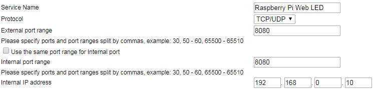
Also a big advantages if you have a static IP from your ISP. Dynamic will do but after restarting the router the external IP will change. You can find out your current external IP from this website https://www.whatismyip.com. So if my IP comes up as 160.153.129.223 then I need to go to 160.153.129.223:8080 to open the Pi’s website. It all depends on what port is forwarded to 8080.
One thought on “Raspberry Pi Web Server – RGB LED Control Over The Internet”
Hi, Thank you for the really good explanation. I was able to deploy the first war file with the “Hello World” output. The next steps were straight forward and I was able to build the application. The problem is whey I deploy the war to tomcat. Tomcat is not able to start up again at all. If I remove the war and the application from webapps folder it works. Any advise or tips?
Thank you!!